| CPC G01B 7/30 (2013.01) | 24 Claims |

|
1. A method for measuring the mechanical angular position (θm) of a rotor, the rotor being movable in multi-turn rotation about an axis of rotation (A1) with respect to a stator, the method comprising:
acquiring a number Ns of electrical measurement signals (S1, S2) each representative of an intensity of an electrical or magnetic variable at one of a number Ns of measurement locations (P1, P2), the Ns measurement locations being separate, fixed with respect to the stator and offset by a given mechanical angle (“alpha”) about the axis of rotation, Ns being an integer equal to 2 or 3;
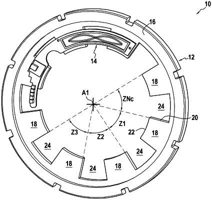
the variation in the electrical measurement signal at a measurement location is caused by the rotation, in front of the measurement location under consideration, of a target (12) mechanically linked to the rotor and having a number Nc, greater than or equal to 2, of separate contrast areas (Zk) of the target, in which the target includes a contrast in electrical conductivity, magnetic permeability and/or magnetization;
the contrast areas (Zk) are angularly distributed across the target in a periodic pattern about the axis of rotation, the pattern having Nc pattern quasi-periods, each contrast area extending over a mechanical angle of 2Pi/Nc about the axis of rotation;
each contrast area (Zk) is such that the passing, in rotation about the axis of rotation, of a contrast area in front of each measurement location induces a variation in the electrical measurement signal (S1, S2) acquired at this location which is a quasi-sinusoidal function of an electrical angular position (θe) of the contrast area with respect to the measurement location, the electrical angular position (θe) varying by 2Pi radians for a 2Pi/Nc radians variation in the mechanical angular position (θm) of the target about the axis of rotation;
at least two of the contrast areas Zk have a physical difference between one another which creates, between at least two separate quasi-periods of the measurement signal, over one and the same turn of the target, a difference in the amplitude of the intensity of the physical variable measured in said at least two separate quasi-periods of the measurement signal respectively;
wherein the measurement locations are offset about the axis of rotation by a corresponding mechanical angle (alpha), modulo 2Pi/Nc radians of angle, to Pi/(2×Nc) radians for Ns=2 and 2Pi/3Nc radians for Ns=3; and
wherein the method includes, during a calibration phase, then again during a setting phase of a measurement session:
a) acquiring, over one mechanical turn of the target about the axis of rotation, the Ns electrical measurement signals (S1, S2);
b) computing, for different mechanical angular positions over one mechanical turn of the target about the axis of rotation, an instantaneous value of the electrical angular position (θe) for the mechanical angular position under consideration, by a law of calculation of the electrical angular position taking into account:
for Ns=2, the arctangent of the ratio of the values of the two measurement signals (S1, S2) for the time under consideration, or
for Ns=3, the arctangent of the ratio of the values of the two transforms obtained by a Clarke transform, applied to the three measurement signals for the time under consideration;
c) computing an instantaneous incremented electrical angular position value (θe_inc), obtained by incrementing a counter X by one unit for any 2PI radians variation in the electrical angular position (θe), this variation occurring in the same direction of rotation;
d) determining by a computer at least one electrical signature of the target, comprising an electrical calibration signature determined during the calibration phase and an electrical setting signature determined during the setting phase, each electrical signature being determined by a pair of signature values or a series of pairs of signature values, a pair of signature values comprising:
a magnitude signature value, derived from at least one of the values of at least one of the measurement signals for at least one angular position of the target; and
an angular position signature value for the angular position or positions of the target corresponding to the instantaneous magnitude value or values that were taken into account to determine the magnitude signature value;
wherein, during the calibration phase, the electrical calibration signature of the target is recorded by a computer;
wherein, during the setting phase of a measurement session, an angular offset measurement value (delta_i_θm0) is determined by a resetting operation comprising the calculation of the angular measurement offset value, which, applied to the angular position signature values of the electrical setting signature or of the electrical calibration signature, makes it possible to minimize the difference between the electrical setting signature and the electrical calibration signature; and
wherein, during the measurement session, the mechanical angular position (θm) of the rotor at a given time is determined by correcting the incremented electrical angular position by an amount equal to the angular measurement offset value, and
wherein the electrical measurement signal is a voltage, a current, or a magnetic field, and wherein the electrical or magnetic quantity is a voltage, a current, or a magnetic field.
|