| CPC F24F 9/00 (2013.01) [F24F 11/79 (2018.01); F24F 13/072 (2013.01); F24F 2009/007 (2013.01); F24F 2120/12 (2018.01)] | 16 Claims |

|
1. A hygiene management device for an entrance hall, the hygiene management device comprising:
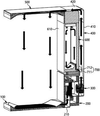
a fan assembly configured to generate a flow of air;
a duct unit configured to receive air flow from the fan assembly;
an air discharger configured to:
receive air from the duct unit; and
discharge the received air toward a person; and
a function module including:
a storage space;
an inflow path configured to receive air from the duct unit, the inflow path including an air inlet and an air outlet; and
an opening/closing unit configured to:
selectively open or close air flow to the function module; and
selectively open or close air flow to the duct unit,
wherein the hygiene management device has an upper part provided on an upper portion of the entrance hall and defined as an upper wall, a bottom part provided on a floor of the entrance hall and defined as a lower wall, and a sidewall part provided on a side of the entrance hall and defined as a side wall,
wherein the fan assembly is provided at a lower portion of the sidewall part,
wherein the function module is provided at an upper portion of the sidewall part,
wherein the air discharger is provided in the upper part,
wherein the duct unit includes:
a first duct provided along a rear of the function module in the sidewall part and connected to the fan assembly, and
a second duct provided on an upper portion of the function module and receiving air passing through the first duct and supplying the received air to the air discharger,
wherein the air inlet of the inflow path is formed through a rear surface of the function module so as to communicate with an inside of the first duct, and
wherein the air outlet of the inflow path opens into an inside of the function module,
wherein the opening/closing unit includes:
a first shutter located in the first duct; and
a second shutter located in the inflow path,
wherein the first shutter is configured to open both the first duct and a communication portion of the inflow path, or to open only the inflow path, and
wherein the second shutter selectively closes the inflow path regardless of whether the first duct is open.
|