| CPC F16K 3/085 (2013.01) [B29C 64/124 (2017.08); B29C 64/364 (2017.08); B41F 13/22 (2013.01); B41F 23/0476 (2013.01); F16K 3/32 (2013.01); F16K 3/34 (2013.01); G05D 9/12 (2013.01); H01L 21/67276 (2013.01); B33Y 30/00 (2014.12); B33Y 50/02 (2014.12)] | 12 Claims |

|
1. An automatic refilling system, comprising:
a flow control equipment, wherein the flow control equipment, comprises:
a housing, comprising a discharge hole, the discharge hole being in a bottom of the housing;
a liquid inlet tube, connecting with a top of the housing;
a motor, located in the housing;
a flow locking blade and a plurality of flow control blades, connected to the motor, wherein leakage holes of different sizes are formed in the flow control blades, and the motor drives the flow control blades and the flow locking blade to rotate to align the different leakage holes with the discharge hole, or to seal the discharge hole;
a liquid outlet tube, connecting with the discharge hole;
a liquid supply equipment, connected to the liquid inlet tube, and configured to provide a liquid;
a controller, connected to the flow control equipment, and configured to control the motor to rotate the flow locking blade or the flow control blades to a position above the discharge hole;
a liquid buffering groove, connected to the liquid outlet tube; and
a liquid tank, located below the liquid buffering groove, and configured to accommodate the liquid; and,
wherein
a plurality of drainage holes having a same height or different heights are formed in a bottom or a sidewall of the liquid buffering groove; and the automatic refilling system further comprises:
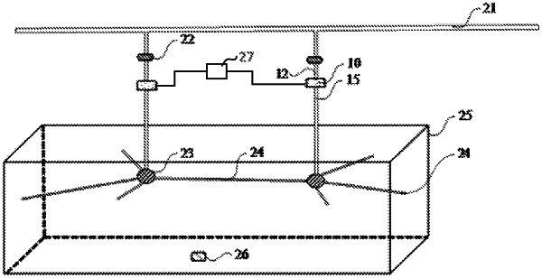
a plurality of drainage tubes, connected to the drainage holes, and configured to drain the liquid in the liquid buffering groove to a sidewall of the liquid tank.
|