| CPC F16C 32/0648 (2013.01) | 3 Claims |

|
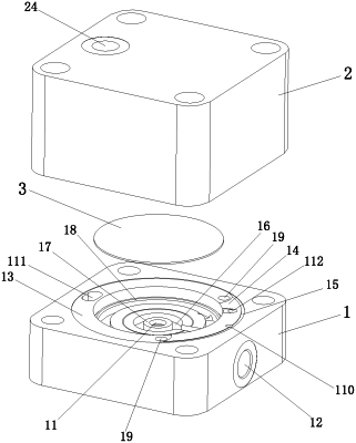
1. A flow control method for a hydrostatic device, comprising: a main body (1) and an auxiliary body (2) matched with the main body (1), wherein the center of the main body (1) is provided with an oil filling hole (11), a side edge of the main body (1) is provided with an oil outlet hole (12), and the oil filling hole (11) is communicated with the oil outlet hole (12); the upper surface of the main body (1) forms a first flow channel (13), a lug boss (14) is formed on the first flow channel (13), and the surface of the lug boss (14) is higher than the surface of the first flow channel (13), so that oil of the first flow channel (13) does not flow to the lug boss (14); the upper surface of the main body (1) forms a second flow channel (15); the second flow channel (15) is communicated with the first flow channel (13), and the surface of the second flow channel (15) is higher than the surface of the first flow channel (13); the oil of the first flow channel (13) can enter the second flow channel (15);
the middle of the main body (1) is concave down to form a pressure stabilizing cavity (16), and the pressure stabilizing cavity (16) and the end surface of the oil filling hole (11) are formed with a throttling platform (17); the end of the first flow channel (13) is provided with more than one first throttling hole (19), and the more than one first throttling hole (19) is communicated with the pressure stabilizing cavity (16), so that the oil enters the pressure stabilizing cavity (16) from the first flow channel (13); the second flow channel (15) is provided with a main oil hole (110), and the main oil hole (110) is communicated with the oil outlet hole (12); the first flow channel (13) is provided with an oil distribution channel (111); the lug boss (14) is provided with a second throttling hole (112); the second throttling hole (112) is communicated with the oil distribution channel (111); and the oil of the oil distribution channel (111) enters the second throttling hole (112);
a bump (21) matched with a bearing platform (18) is formed on the bottom of the auxiliary body (2); when the auxiliary body (2) is matched with the main body (1), the bump (21) is matched with the bearing platform (18), and a film sheet (3) is arranged between the bump (21) and the bearing platform (18); the surface of the bump (21) is provided with a groove (22), and one end of the groove (22) is matched with the second throttling hole (112); the oil from the second throttling hole (112) enters the groove (22) and then reaches a regulating cavity (23) formed between the film sheet (3) and the bump (21); the auxiliary body (2) is provided with an oil inlet hole (24); and when the auxiliary body (2) is matched with the main body (1), the oil inlet hole (24) is communicated with the first flow channel (13);
the main body (1) and the auxiliary body (2) are matched to jointly form a flow controller; the closed first flow channel (13) and the second flow channel (15) are formed on a joint end surface of the main body (1) and the auxiliary body (2); the film sheet (3) is predeformed under the pressure effect of the main body (1) and the auxiliary body (2) to form the regulating cavity (23) and the pressure stabilizing cavity (16) that are not communicated with each other; hydraulic oil enters the flow controller formed by matching the main body (1) and the auxiliary body (2) from the oil inlet hole (24) with pump pressure; after entering, the hydraulic oil is divided into two streams of oil; one stream of oil passes through the first flow channel (13); and wherein the more than one first hole comprising two first holes and the one steam of the oil that passes through the first flow channel (13) enters the pressure stabilizing cavity (16) through the two first throttling holes (19) respectively, and enters the main oil hole (110) through the second flow channel (15); the other stream of oil enters the second throttling hole (112) through the oil distribution channel (111) and enters the regulating cavity (23) through the groove (22); and oil pressure in the regulating cavity (23) deforms the film sheet (3) so that the film sheet (3) is matched with the throttling platform (17).
|