| CPC F01N 3/2892 (2013.01) [B01D 53/9431 (2013.01); B01F 23/2132 (2022.01); B01F 25/103 (2022.01); B01F 25/3141 (2022.01); B01F 25/4316 (2022.01); B01F 35/55 (2022.01); F01N 3/2066 (2013.01); B01F 2025/913 (2022.01); F01N 2610/1453 (2013.01)] | 20 Claims |

|
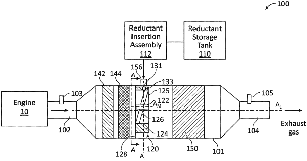
1. An aftertreatment system for treating constituents of an exhaust gas produced by an engine, comprising:
a housing defining a housing central axis;
a selective catalytic reduction (SCR) system disposed in the housing;
a mixer disposed in the housing upstream of the SCR system, the mixer comprising:
a hub,
a tubular member disposed circumferentially around the hub and defining a reductant entry port extending radially through the tubular member, and
a plurality of vanes extending from the hub to the tubular member such that openings are defined between adjacent vanes of the plurality of vanes to allow the exhaust gas to flow therethrough such that the plurality of vanes swirl the exhaust gas in a circumferential direction with respect to an exhaust gas flow path of the exhaust gas; and
a reductant injector disposed on the housing upstream of the SCR system and configured to insert reductant into the exhaust gas flowing through the housing through the reductant entry port, wherein the reductant injector is configured to insert the reductant such that, in a view along the housing central axis, a direction of the reductant insertion is at a non-zero angle with respect to a transverse axis of the housing that extends through the reductant injector and through the housing central axis,
wherein a mixer central axis of the mixer defined through the hub is radially offset with respect to the housing central axis.
|