| CPC C12M 23/40 (2013.01) [C12M 23/26 (2013.01); C12M 23/28 (2013.01)] | 13 Claims |

|
1. A flow distribution device for bioprocess systems, comprising:
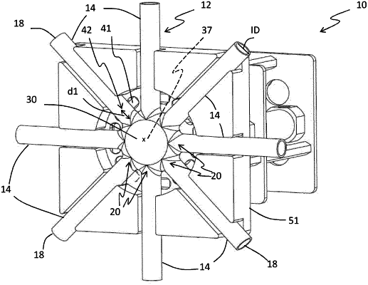
a flow distribution manifold comprising:
at least four fluid connection tubes, wherein each fluid connection tube comprises a first end for fluid connection and an opposite second end, and wherein at least three of the fluid connection tubes comprise at least one flexible part which can be compressed for preventing fluid flow between the first and second end of the fluid connection tube; and
a central common compartment to which the second ends of each of the fluid connection tubes are connected, whereby the first ends of each of the fluid connection tubes can be in fluid communication with the central common compartment and wherein the fluid connection tubes are entering the central common compartment from at least three different directions;
wherein said flow distribution device further comprises
at least three pinching members positioned within a cavity surrounding the central compartment which are provided in connection with one fluid connection tube of the flow distribution manifold each, wherein each of said pinching members can be controlled into at least a first and a second position, wherein in the first position for each of the pinching members the pinching member pinches one of the fluid connection tubes such that fluid flow is prevented between the first end and the second end of this fluid connection tube and in the second position the pinching member is provided in a position such that fluid flow is allowed between the first end and the second end of the fluid connection tube; and
wherein a distance from the second end of at least one of the fluid connection tubes to a second end of an adjacent fluid connection tube is smaller than the distance between two pinching members configured for pinching the same two fluid connection tubes.
|