| CPC B25J 9/1692 (2013.01) [B25J 9/0081 (2013.01); B25J 13/085 (2013.01)] | 10 Claims |
|
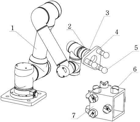
1. A robot calibration method based on pose constraint and force sensing, wherein the robot calibration method is achieved based on a robot calibration device, the robot calibration device comprises an end calibration device, and a geometric constraint device; the end calibration device comprises a force sensor, a connecting seat, and a plurality of calibration spheres; the connecting seat is connected to the force sensor; the calibration spheres are fixed to one end face of the connecting seat; the geometric constraint device comprises a constraint supporting seat, and a plurality of V-shaped grooves which are arranged on the constraint supporting seat and correspond to the number of calibration spheres;
wherein the robot calibration method comprises the following steps:
S1: establishing a model, wherein the model comprises a kinematic model of a robot, a geometric error model based on pose constraint, and a non-geometric error model;
S2: measuring and installing, comprising measuring a first relative pose of each calibration sphere on the end calibration device relative to the connecting seat, and a second relative pose between the V-shaped grooves on the geometric constraint device, installing the end calibration device to an end of the robot after measuring, and installing the geometric constraint device into a working space of the robot;
S3: collecting data, comprising changing a position of the geometric constraint device in the working space of the robot by many times, dragging the robot at each position to make various calibration spheres of the end calibration device correspondingly constrained in the V-shaped grooves on the geometric constraint device, changing a magnitude and direction of a force exerted on an end of the end calibration device for many times, enabling various calibration spheres to touch the V-shaped grooves in different faces on the geometric constraint device in a same way, and reading and recording joint angle data and force sensor data after each measurement operation is stable;
S4: identifying parameters, comprising dividing the joint angle data and the force sensor data into a plurality of groups according to different geometric constraint device poses, and then dividing the plurality of groups of data into a plurality of sub-groups according to different faces where the V-shaped grooves are located, and substituting data with the smallest indication of the force sensors in a same group but different sub-groups into the geometric error model in pairwise; substituting the same group of data into the non-geometric error model, training the data by machine learning, and then adding an identified non-geometric error model to the kinematic model after geometric parameter identification to identify parameters of the kinematic model of the corresponding robot; and
S5: compensating error, comprising compensating an identified parameter error of the kinematic model to a controller of the robot.
|