| CPC B25B 21/02 (2013.01) [B25F 5/006 (2013.01)] | 20 Claims |

|
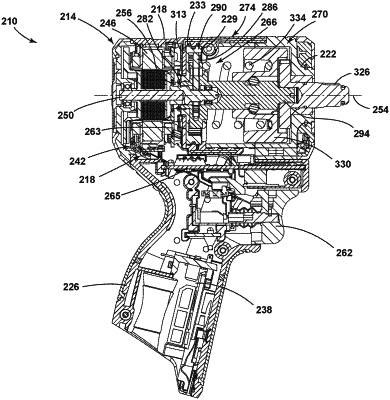
1. A power tool comprising:
a housing having a first housing portion and a second housing portion coupled to the first housing portion;
a motor directly mounted within the housing between the first and second housing portions and including an output shaft, the output shaft defining an axis;
a gear assembly supported within the housing and operably coupled to the motor, the gear assembly including a ring gear directly supported by the first and second housing portions, a pinion gear coupled for co-rotation with the output shaft, and a plurality of planet gears meshed with the pinion gear and the ring gear; and
a drive assembly operably coupled to the gear assembly, the drive assembly including a camshaft, an anvil, a hammer configured to reciprocate along the camshaft to impart rotational impacts to the anvil in response to rotation of the camshaft, and a spring biasing the hammer towards the anvil,
wherein the ring gear includes a plurality of lugs engaged with the first housing portion and the second housing portion to rotationally constrain the ring gear.
|