| CPC A61M 16/0003 (2014.02) [A61M 16/0066 (2013.01); A61M 16/1075 (2013.01); A61M 39/08 (2013.01); A61M 2205/0216 (2013.01); A61M 2205/07 (2013.01); A61M 2205/3327 (2013.01); A61M 2205/3368 (2013.01)] | 17 Claims |

|
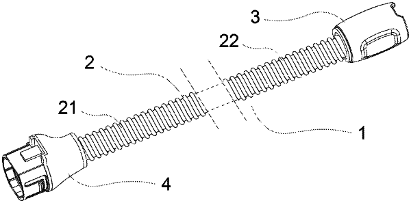
1. A heatable air delivery tube, configured to form a connection with an airflow generator and a patient interface assembly, and to deliver pressurized breathable gas to an airway of a patient, the air delivery tube comprising:
an airflow generator end, which includes a support element, a sealing element, a first clip, and an electrical connector,
wherein the support element and the sealing element are configured to be partially in contact with the airflow generator, and the support element is configured to be interconnected to the sealing element,
wherein the first clip is configured to secure a heated spiral tube, the electrical connector is configured to connect to the airflow generator to form a continuous circuit,
wherein the support element includes a first end and a second end, and the first end is configured to be internally connectable to the sealing element and includes a connecting clamp, wherein the connecting clamp includes a gap and a guiding slanted protrusion, and is configured to be deformably fixed to the airflow generator,
wherein the second end is configured to be externally connectable to the heated spiral tube and the first clip, and the second end includes a positioner in contact with the first clip,
wherein the sealing element includes a third end and a fourth end, with the third end including a clearance at a position corresponding to the connecting clamp, and having an inner diameter not exceeding an outer diameter of an air supply tube of the airflow generator, and wherein the third end is configured to seal the airflow generator, while the fourth end is configured to provide a gripping portion;
the heated spiral tube, configured to connect to a patient interface end at one end and to the airflow generator end at an other end, including metal wires, a compressible flexible wall, and a spring-like coil, together to form the compressible heated spiral tube; and
the patient interface end, configured to connect to the heated spiral tube, including an elastomer to connect to the patient interface assembly, a bracket to connect to the heated spiral tube, and a second clip to secure the heated spiral tube.
|