| CPC A61B 8/54 (2013.01) [A61B 8/085 (2013.01); A61B 8/4477 (2013.01); A61B 8/4488 (2013.01); A61B 8/5269 (2013.01); A61B 8/56 (2013.01); G01S 7/52095 (2013.01)] | 15 Claims |
|
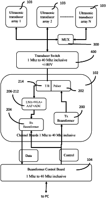
1. A signal processing pathway for an ultrasonic imaging device, the signal processing pathway comprising:
a channel board configured to transmit a transmitted signal to an ultrasonic transducer array, and further configured to receive a received signal from the ultrasonic transducer array further comprises:
a transmit/receive switch for switching between a transmit pathway and a receive pathway;
a transmit beamformer situated in the transmit pathway for controlling a timing and a shape of the transmitted signal;
a pulser situated in the transmit pathway between the transmit beamformer and the transmit/receive switch for adjusting a voltage of the transmitted signal;
a receive beamformer situated in the receive pathway for storing and transferring, at least in part, the received signal;
an ADC (analog/digital converter) situated in the receive pathway between the transmit/receive switch and the receive beamformer for converting the received signal;
a VGA (variable gain amplifier) situated in the receive pathway between the transmit/receive switch and the receive beamformer for amplifying selected properties of the received signal;
an AAF (anti-aliasing filter) situated in the receive pathway between the transmit/receive switch and the receive beamformer for preventing aliasing and for limiting a noise of the received signal; and
a LNA (low noise amplifier) situated in the receive pathway between the transmit/receive switch and the receive beamformer for amplifying the received signal; and
a beamformer control board configured to control the channel board;
wherein, the channel board and the beamformer control form the receive pathway and the transmit pathway that each have a bandwidth across a frequency range of 1 MHz to 40 MHz inclusive and for voltages within a range of −80V to +80V inclusive, the received signal traverses the receive pathway and the transmitted signal traverses the transmit pathway.
|