| CPC F16H 37/082 (2013.01) [B60K 1/00 (2013.01); B60K 17/16 (2013.01); F16H 48/08 (2013.01); F16H 57/021 (2013.01); F16H 57/037 (2013.01); F16H 2057/02034 (2013.01); F16H 2057/02043 (2013.01)] | 6 Claims |

|
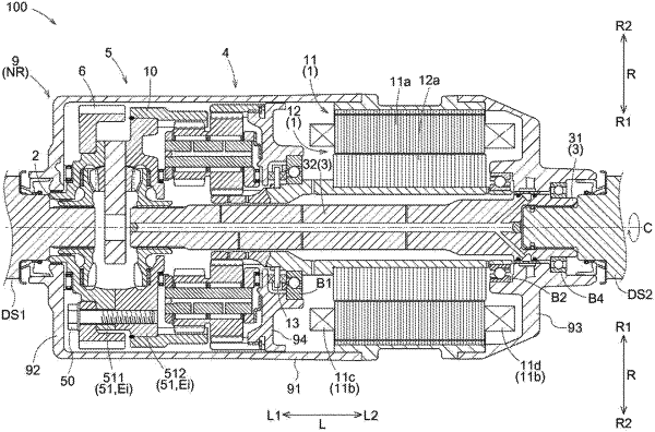
1. A vehicle drive device, comprising:
a rotating electrical machine including a rotor;
a first output member drivingly connected to a first wheel;
a second output member drivingly connected to a second wheel;
a planetary gear mechanism that reduces a speed of rotation of the rotor;
an output differential gear mechanism that includes an input element and that distributes rotation transmitted from the planetary gear mechanism to the input element to the first output member and the second output member; and
a case housing the rotating electrical machine, the planetary gear mechanism, and the output differential gear mechanism, wherein
the rotating electrical machine, the first output member, the second output member, the planetary gear mechanism, and the output differential gear mechanism are disposed coaxially,
the planetary gear mechanism includes a first rotating element, a second rotating element, a third rotating element, and a fourth rotating element, and is configured in such a manner that rotational speeds of the first to fourth rotating elements are in an order of the first rotating element, the second rotating element, the third rotating element, and the fourth rotating element,
the first rotating element is a first sun gear connected to the rotor so as to rotate with the rotor,
the third rotating element is a first ring gear connected to the case,
the fourth rotating element is a second ring gear connected to the input element so as to rotate with the input element,
the second rotating element is a first carrier rotatably supporting a first pinion gear and a second pinion gear that rotate together,
the first pinion gear meshes with the first sun gear and the first ring gear,
the second pinion gear has a smaller diameter than the first pinion gear and meshes with the second ring gear,
the first sun gear is supported in a radial direction with respect to the case via a first support bearing, and the second ring gear and the input element are connected in such a manner that relative movement between the second ring gear and the input element in the radial direction is restricted, the radial direction being a direction perpendicular to a rotation axis of the rotor,
the planetary gear mechanism is disposed on a first side in an axial direction with respect to the rotor,
the output differential gear mechanism is disposed on the first side in the axial direction with respect to the planetary gear mechanism,
the input element is supported in the radial direction with respect to the case via a second support bearing disposed on the first side in the axial direction with respect to a plurality of gears constituting the output differential gear mechanism, the axial direction being a direction along the rotation axis of the rotor, the first side in the axial direction being one side in the axial direction, and a second side in the axial direction being the other side in the axial direction,
the output differential gear mechanism includes a differential case, a shaft member disposed so as to be supported by the differential case and extend in the radial direction, a first bevel gear housed in the differential case and rotatably supported by the shaft member, and a pair of second bevel gears housed in the differential case and meshing with the first bevel gear on both sides in the axial direction with respect to the shaft member,
the differential case is the input element,
the first output member is disposed on the first side in the axial direction with respect to the second output member,
the second output member is disposed so as to extend through an inner side in the radial direction of a differential case target portion in the axial direction, and
a third support bearing is disposed between an inner peripheral surface of the differential case target portion and an outer peripheral surface of the second output member, the differential case target portion being a part of the differential case that is located on the second side in the axial direction with respect to a middle position in the axial direction of the output differential gear mechanism.
|