| CPC E21B 43/2607 (2020.05) [F04B 11/0008 (2013.01); F15B 2201/40 (2013.01)] | 20 Claims |

|
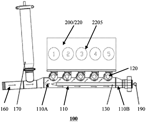
1. A low-pressure liquid inlet manifold, comprising:
a main liquid inlet pipe, comprising a first end and a second end that are arranged opposite to each other in an extension direction of the main liquid inlet pipe;
N liquid feeding pipes, arranged in sequence along a direction from the first end to the second end, wherein each of the N liquid feeding pipes comprises a third end and a fourth end that are arranged opposite to each other in an extension direction of the each of the N liquid feeding pipes, the third end is communicated with the main liquid inlet pipe, and the fourth end is configured to provide low-pressure liquid to a plunger pump; and
at least one auxiliary accumulator, the at least one auxiliary accumulator being connected with the main liquid inlet pipe and arranged corresponding to at least one of the N liquid feeding pipes, an orthographic projection of the auxiliary accumulator on an axis of the main liquid inlet pipe overlapping with an orthographic projection of a corresponding liquid feeding pipe on the axis, and N being a positive integer greater than or equal to 2,
wherein each of the at least one auxiliary accumulator comprises:
a top plate in contact with fluid in the main liquid inlet pipe and configured to move along a movement direction; and
a pressure applying portion located on a side of the top plate away from the main liquid inlet pipe, and configured to apply energy storage pressure to the top plate.
|