| CPC B60T 8/17 (2013.01) [B60T 7/042 (2013.01); B60T 7/06 (2013.01); B60T 8/96 (2013.01); B60T 17/22 (2013.01); B60Y 2400/81 (2013.01)] | 6 Claims |

|
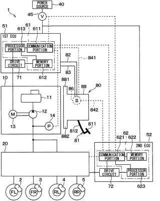
1. A vehicle brake system comprising:
a vehicle brake device including:
a brake pedal including a pedal part and a lever part rotatable about a rotational shaft according to an operation of the pedal part;
a stroke sensor configured to output a signal in accordance with a stroke amount of the brake pedal;
a housing rotatably supporting the lever part and being located in a vehicle compartment of a vehicle and on a partition wall that separates an outside of the vehicle compartment and an inside of the vehicle compartment; and
a reaction force generator connected to the housing and the lever part and configured to generate a reaction force on the lever part in accordance with the stroke amount;
a first floid pressure generator configured to generate a fluid pressure for braking the vehicle;
a second fluid pressure generator configured to generate a fluid pressure for braking the vehicle; and
a fluid pressure controller configured to control the fluid pressure generated by the first fluid pressure generator and the fluid pressure generated by the second fluid pressure generator based on the signal from the stroke sensor, wherein
the stroke sensor is a first stroke sensor,
the vehicle brake device farther includes a second stroke sensor configured to output a signal in accordance with the stroke amount,
the fluid pressure controller is a first fluid pressure control ured to control the fluid pressure generated by the first fluid pressure generator,
the vehicle brake system further comprising:
a second fluid pressure controller configured to control the fluid pressure generated by the second fluid pressure generator;
a first power source configured to supply power to the first fluid pressure controller; and
a second power source configured to supply power to the second fluid pressure controller, wherein
the vehicle brake device further includes:
a first sensor power source wire connected to the first fluid pressure controller and the first stroke sensor and configured to supply the power of the first power source from the first fluid pressure controller to the first stroke sensor; and
a second sensor power source wire connected to the second fluid pressure controller and the second stroke sensor and configured to supply the power of the second power source from the second fluid pressure controller to the second stroke sensor.
|