| CPC B25J 9/02 (2013.01) [G01B 5/0021 (2013.01); G01B 5/004 (2013.01)] | 4 Claims |
|
1. A robotic arm calibration method, the method applied to a robotic arm and comprising steps of:
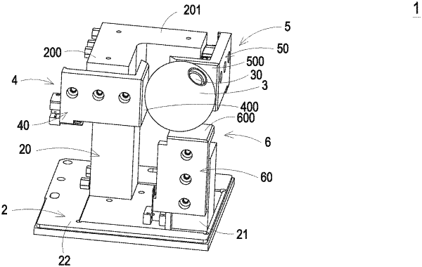
(S1) providing a three-dimensional measuring device, wherein the three-dimensional measuring device comprises a ball-shaped structure, a base, an X-axis measuring module, a Y-axis measuring module and a Z-axis measuring module, wherein the ball-shaped structure is assembled with the robotic arm, the ball-shaped structure is moved and/or rotated in response to a movement of the robotic arm, the X-axis measuring module is disposed on the base and comprises a first measuring structure and a first position sensor, the first measuring structure is movable along an X-axis direction and contacted with the ball-shaped structure, and the first position sensor measures a displacement amount of the first measuring structure when the first measuring structure is pushed by the ball-shaped structure, wherein the Y-axis measuring module is disposed on the base and comprises a second measuring structure and a second position sensor, the second measuring structure is movable along a Y-axis direction and contacted with the ball-shaped structure, and the second position sensor measures a displacement amount of the second measuring structure when the second measuring structure is pushed by the ball-shaped structure, wherein the Z-axis measuring module is disposed on the base and comprises a third measuring structure and a third position sensor, the third measuring structure is movable along a Z-axis direction and contacted with the ball-shaped structure, and the third position sensor measures a displacement amount of the third measuring structure when the third measuring structure is pushed by the ball-shaped structure, wherein a measuring space is defined by a movable distance range of the first measuring structure along the X-axis direction, a movable distance range of the second measuring structure along the Y-axis direction and a movable distance range of the third measuring structure along the Z-axis direction, wherein when the ball-shaped structure is moved in the measuring space, a three-dimensional coordinate of the ball-shaped structure is obtained according to sensed results of the first position sensor, the second position sensor and the third position sensor;
(S2) calculating at least one preset positioning point in the measuring space;
(S3) controlling the robotic arm to be moved from an initial point toward the same preset positioning point with different operation actions for more than two times, and acquiring a three-dimensional coordinate of each actual positioning point of the robotic arm at each time according to the three-dimensional coordinate of the ball-shaped structure measured by the three-dimensional measuring device;
(S4) calculating a function equation about each actual positioning point in each operation action of the robotic arm in the step (S3) according to the forward kinematics, and acquiring a predicted positioning point of the robotic arm in each operation action according to the function equation;
(S5) judging whether a difference between the predicted positioning points of the robotic arm in every two different operation actions minus a difference between the actual positioning points of the robotic arm in every two different operation actions is within an acceptable threshold range; if the difference between the two predicted positioning points minus the difference between the two actual positioning points is within the acceptable threshold range, the robotic arm calibration method is ended;
(S6) if a judging result of the step (S5) is not satisfied, generating a Jacobian matrix according to the reached actual positioning point in each operation action of the robotic arm, and acquiring a position formula about the predicted positioning point and the actual positioning point in each operation action of the robotic arm, wherein the Jacobian matrix is a partial derivative of the function equation corresponding to a deviation amount Δα of a shaft size α of each axis of the robotic arm and a deviation amount Δθ of a rotation angle θ of each axis of the robotic arm in the corresponding operation action under the forward kinematics;
(S7) performing a subtraction on the position formulae corresponding every two operation actions of the robotic arm, so that a difference between the deviation amounts Δα and a difference between the deviation amounts Δθ in every two operation actions are calculated; and
(S8) updating the shaft size α of each axis and the rotation angle θ of each axis according to the difference between the deviation amounts Δα and the difference between the deviation amounts Δθ, and performing the step (S4) again.
|