| CPC B06B 1/0223 (2013.01) [B06B 1/0215 (2013.01); B06B 1/0688 (2013.01); G06F 3/016 (2013.01); H10N 30/802 (2023.02)] | 19 Claims |

|
1. A driver circuit for driving a transducer based on an input signal comprising:
a switching output stage having first and second output nodes for driving said transducer in a bridge-tied-load configuration; and
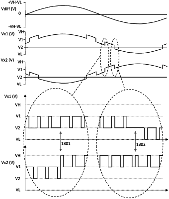
a controller configured to control the switching output stage based on the input signal so as to modulate each of the first and second output nodes between a respective pair of switching voltages at a respective duty cycle in a switching cycle,
wherein the controller is operable in at least:
a first mode in which the first output node is modulated between a first pair of switching voltages and the second output node is modulated between a second pair of switching voltages; and
a second mode in which the first output node is modulated between a third pair of switching voltages and the second output node is modulated between said second pair of switching voltages, wherein at least one of the switching voltages of the third pair of switching voltages is different to a switching voltage of the first pair of switching voltages;
wherein the controller is configured to transition between the first mode and the second mode by:
applying a variation in the duty cycle of modulation of the second output node between the second pair of switching voltages; and
within a switching cycle of applying said variation in the duty cycle of modulation of the second output node, changing the modulation of the first output node from the first pair of switching voltages to the third pair of switching voltages or vice versa.
|