| CPC A61N 1/0551 (2013.01) [A61N 1/3752 (2013.01)] | 16 Claims |

|
1. An implantable electrical stimulation medical system comprising:
an implantable medical device having electrical circuitry configured to deliver electrical stimulation;
an implantable medical lead having a plurality of connectors that are at least one of sized or spaced so that the implantable medical lead is incompatible to be directly coupled to connectors within the implantable medical device; and
an adapter matrix configured to electrically interface with the electrical circuitry and the implantable medical lead to provide electrical stimulation from the implantable medical device to the implantable medical lead,
wherein the adapter matrix comprises:
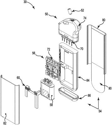
a neurostimulator implantable pulse generator (IPG)-facing input having a first set of electrical connections that face the implantable medical device and a tissue-facing input having a second set of electrical connections, the second set of electrical connections includes a plurality of conductive microprobes, the first set of electrical connections selectively electrically coupleable to the second set of electrical connections,
wherein the first set of electrical connections are configured to electrically interface with the electrical circuitry, and wherein the second set of electrical connections having the plurality of conductive microprobes are configured to electrically interface with the implantable medical lead to deliver electrical stimulation from the implantable medical device to the implantable medical lead,
wherein two or more conductive microprobes of the plurality of conductive microprobes are configured to electrically interface with a single connector of the plurality of connectors of the implantable medical lead,
wherein the adapter matrix includes a first switch and a second switch,
wherein a first electrical connection of the first set of electrical connections is coupled to a first side of the first switch and a first side of the second switch,
wherein a first conductive microprobe of the two or more conductive microprobes is coupled to a second side of the first switch, and
wherein a second conductive microprobe of the two or more conductive microprobes is coupled to a second side of the second switch,
wherein the system further comprises control logic circuitry configured to determine that the first conductive microprobe and the second conductive microprobe are coupled to the single connector based on an impedance between the first conductive microprobe and the second conductive microprobe indicating that the first conductive microprobe and the second conductive microprobe are shorted together.
|