| CPC H03K 17/56 (2013.01) | 20 Claims |

|
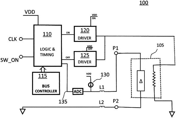
1. A switch circuit arrangement, comprising:
a control circuit;
a plurality of measurement circuits coupled to the control circuit, each measurement circuit comprising a current source; and
a corresponding plurality of switches respectively coupled to measurement circuits of the plurality of measurement circuits,
wherein the control circuit comprises a read mode of operation that is configured, selected switch by selected switch, to:
i) activate the current source to inject current through the selected switch, and
ii) based on the current injected through the selected switch, read, through the measurement circuit, a resulting voltage to measure a programming status of the selected switch;
wherein the read mode of operation is a sequential read mode of operation; and
wherein the plurality of switches are arranged to include through switches and shunt switches, wherein
each through switch has a first through switch terminal coupled to a respective measurement circuit and a second through switch terminal, the first through switch terminal and the second through switch terminal configured to be selectively coupled to an RF signal, and
each shunt switch has a first shunt switch terminal coupled to a respective measurement circuit and configured to be selectively coupled to the RF signal and a second shunt switch terminal coupled to a reference voltage or ground.
|