| CPC H02M 3/07 (2013.01) [H02M 3/158 (2013.01); H02M 7/4833 (2021.05); H02M 7/4837 (2021.05); H02M 1/0095 (2021.05)] | 12 Claims |

|
7. A multi-level power converter including:
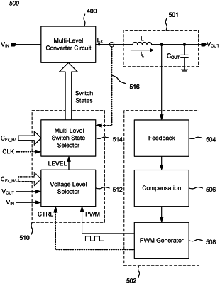
(a) a multi-level converter circuit including (i) a set of switches configured to be serially coupled between a first terminal and a second terminal, and (ii) a set of fly capacitors, each fly capacitor being coupled between a pair of low-side switches among the set of switches and between a pair of high-side switches among the set of switches, the multi-level converter circuit configured to receive an input voltage on the first terminal and produce an output voltage on an output terminal, wherein the output terminal is configured to be coupled to a first terminal of an inductor;
(b) a feedback controller coupled to a second terminal of the inductor and configured to produce a signal indicative of a voltage at the second terminal of the inductor;
(c) a multi-level controller coupled to the feedback controller and to the multi-level converter circuit, and configured to receive at least the signal from the feedback controller and a respective voltage status signal from the multi-level converter circuit corresponding to a respective fly capacitor among the set of fly capacitors, wherein the multi-level controller is configured to charge-balance each fly capacitor among the set of fly capacitors during a switching cycle of the multi-level converter circuit in response to the received signals by:
(1) selecting one fly capacitor among the set of fly capacitors that has not previously been selected;
(2) if a voltage on the selected fly capacitor is above an associated target voltage and there are remaining low-side or high-side switches among the set of switches that are currently closable to enable a discharge path for the selected fly capacitor, then (i) setting the remaining low-side or high-side switches that enable the discharge path for the selected fly capacitor to a closed state, and otherwise (ii) setting the remaining low-side or high-side switches that enable a charging path for the selected fly capacitor to a closed state;
(3) looping to step (c)(1) until all fly capacitors among the set of fly capacitors have been selected; and
(4) for a remaining pair of left-over switches among the set of switches, setting an associated high-side switch or an associated low-side switch among the set of switches to a closed state based on a set of switch count rules, wherein the multi-level converter circuit has M total levels and the set of switch count rules for a level m of the multi-level converter circuit includes:
(a) M−m low-side switches among the set of switches must be closed;
(b) m−1 high-side switches among the set of switches must be closed; and
(c) low-side switches and high-side switches among the set of switches that are not required to be closed must be open.
|