| CPC H02J 50/12 (2016.02) [B60L 53/122 (2019.02); B60L 53/124 (2019.02); B60L 53/126 (2019.02); B60L 53/38 (2019.02); H01F 38/14 (2013.01); H02J 7/00304 (2020.01); H02J 7/00308 (2020.01); H02J 50/90 (2016.02); H02J 7/00309 (2020.01)] | 4 Claims |
|
1. A wireless power transmitter configured to transfer power to a wireless power receiver, comprising:
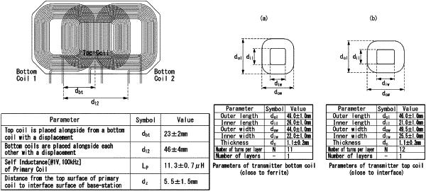
primary coils comprising first and second bottom coils placed adjacent to each other in a line and each consisting of a single layer of 11 turns and a top coil stacked on the first and second bottom coils and consisting of a single layer of 12 turns;
a shielding; and
a full-bridge inverter,
wherein the first and second bottom coils and the top coil have a substantially rectangular frame structure with a through hole in the center,
wherein the top coil lies on a plane surface in the middle between the first and second bottom coils,
wherein a distance from the center of the first and second bottom coils to the center of the top coil is set to a range of 21 mm to 25 mm,
wherein the first and second bottom coils have a height of 48 mm to 50 mm and a width of 43 mm to 45 mm, and the through hole in the first and second bottom coils has a height of 25 mm to 27 mm and a width of 21 mm to 23 mm,
wherein the top coil has a height of 45 mm to 47 mm and a width of 48.5 mm to 50.5 mm, and the through hole in the top coil has a height of 20 mm to 22 mm and a width of 24.5 mm to 26.5 mm,
wherein the first and second bottom coils and the top coil have a thickness of 0.9 mm to 1.3 mm,
wherein an amount of power which is transferred is controlled based on an input voltage of the full-bridge inverter,
wherein the input voltage has a range of 1 V to 18 V,
wherein an operating frequency to control the amount of the power is within a range of 140 kHz to 150 kHz,
wherein an assembly of the primary coils and the shielding has a self-inductance value of 11.3 μH,
wherein the full-bridge invertor drives a series capacitance, and
wherein a value of the series capacitance is 139 nF.
|