| CPC H01R 25/142 (2013.01) [H01R 13/115 (2013.01); H01R 13/18 (2013.01); H02B 1/052 (2013.01); H02B 1/16 (2013.01); H02B 1/20 (2013.01)] | 12 Claims |

|
1. A grounding system for a rackable circuit breaker, comprising:
a finger cluster connector mounted on a grounding bus in a rackable circuit breaker;
a rail conductor mounted in a circuit breaker cradle in a switchgear cabinet and connected to ground potential,
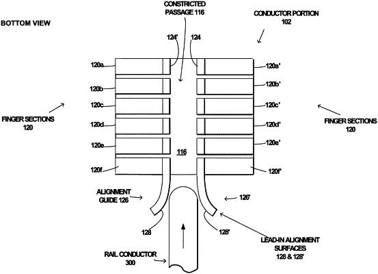
wherein the finger cluster connector comprises a conductor portion formed from a single plate of conductive material folded along a principal direction to form a generally U-shaped body having first side and second side, with respective legs of the U-shaped body on the first and second sides having mutually facing parallel surfaces, each of the legs on the first and second sides being divided into a plurality of finger sections mutually separated by slots, each of the plurality of finger sections extending in length in a direction orthogonal to the principal direction, with distal ends of the finger sections forming the mutually facing parallel surfaces of the legs on the first and second sides separated by a separation distance of forming a constricted passage, and an end finger section on one end of each of the first and second sides having mutually facing surfaces on the distal ends of the end finger sections forming lead-in alignment surfaces for the constricted passage, and
wherein the lead-in alignment surfaces formed by the end finger sections of the conductor portion are configured to align the rail conductor for entry into the constricted passage as the conductor portion slides along the rail conductor in a direction orthogonal to the length of the plurality of finger sections during a rack-in operation of the circuit breaker into the cradle.
|