| CPC H01H 3/28 (2013.01) [G01R 19/16538 (2013.01); H01H 1/221 (2013.01); H01H 1/54 (2013.01); H01H 3/32 (2013.01); H01H 9/54 (2013.01); H01H 37/52 (2013.01); H01H 71/16 (2013.01); H01H 71/2409 (2013.01); H01H 71/28 (2013.01); H01H 73/04 (2013.01); H01H 83/223 (2013.01); H01H 2071/249 (2013.01); H01H 2221/022 (2013.01)] | 25 Claims |

|
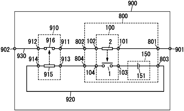
1. A control system for controlling an interrupter, the interrupter being configured to be started by a startup current to interrupt a main electric circuit, the startup current flowing through an auxiliary electric circuit and having a current valve equal to or greater than a predetermined value, the control system comprising:
a driving unit including an intermediate electrical path to be connected to the main electric circuit; and
a driven unit to be connected to the auxiliary electric circuit,
wherein the driving unit is configured to, when an abnormal current having a current value equal to or greater than a prescribed value flows through the intermediate electrical path, use, as a drive source for driving the driven unit, the abnormal current flowing through the intermediate electrical path,
the driven unit is configured to supply the auxiliary electric circuit with the startup current by being driven by the driving unit,
the auxiliary electric circuit is connected to a current supply source configured to supply the startup current,
the driven unit is to be connected to the auxiliary electric circuit in series with the current supply source and is driven by the driving unit to close the auxiliary electric circuit,
the driven unit includes a contact device,
the contact device includes a first contact and a second contact which are to be connected to the auxiliary electric circuit,
the second contact is movable between a closed position where the second contact is in contact with the first contact and an open position where the second contact is out of contact with the first contact,
the driving unit is configured to use the abnormal current flowing through the intermediate electrical path to move the second contact from the open position to the closed position,
the driven unit includes: a first contact device serving as the contact device; and a second contact device,
the first contact device includes:
a first fixed contact serving as the first contact; and
a first moving contact serving as the second contact,
the second contact device includes:
a second fixed contact; and
a second moving contact,
the second fixed contact and the second moving contact are to be connected to the auxiliary electric circuit,
the second moving contact is movable between a closed position where the second moving contact is in contact with the second fixed contact and an open position where the second moving contact is out of contact with the second fixed contact, and
a direction in which the first moving contact moves is different from a direction in which the second moving contact moves.
|