| CPC G05F 1/567 (2013.01) [G05F 3/30 (2013.01); H03F 1/302 (2013.01); H03F 3/085 (2013.01); H03F 3/3432 (2013.01); H03K 17/78 (2013.01); H03F 2200/447 (2013.01); H03F 2200/91 (2013.01)] | 12 Claims |
|
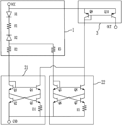
1. A constant current generation circuit for an optocoupler isolation amplifier, comprising a start circuit (1), a current generation circuit and a precision adjustment and output circuit (3) which are integrated into a same substrate, wherein the start circuit (1) can generate and output a first start current and a second start current;
the current generation circuit comprises a negative temperature change rate current generation circuit (21) and a positive temperature change rate current generation circuit (22), wherein the negative temperature change rate current generation circuit (21) is connected with a first start current output end; the positive temperature change rate current generation circuit (22) is connected with a second start current output end; and
the precision adjustment and output circuit (3) is used for outputting a constant current meeting application requirements of the optocoupler isolation amplifier by adjusting proportional precision of two currents outputted from the current generation circuit, wherein the start circuit (1) comprises a diode D1, a resistor R1 and a diode D2 which are connected with a power supply in sequence, wherein an anode of the diode D1 is connected with an output end of the power supply, and a cathode is connected with one end of the resistor R1; another end of the resistor R1 is connected with a cathode of the diode D2; and the first start current output end and the second start current output end are led out from an anode of the diode D2 via resistors R2 and R3, respectively.
|