| CPC G02C 5/08 (2013.01) | 4 Claims |

|
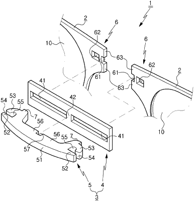
1. An eyeglass frame having foldable bridge comprising:
a pair of rims (2) which face each other and to which lenses (10) are respectively coupled; and
a bridge (3) which is configured to be individually separated from the pair of rims (2), and which is rotatably connected at inner sides facing each other so that the pair of rims (2) are unfolded forwards and folded rearwards,
wherein the bridge (3) comprises:
a connection plate (4) configured such that inner front surfaces of the pair of rims (2) come into contact with both sides thereof, respectively;
and a rotating support (5) coupled to a front of the connection plate (4) such that inner portions of the pair of rims (2) are rotatably coupled to sides of the connection plate (4), with which front surfaces of the pair of rims (2) get in contact, and
wherein the connection plate (4) comprises:
coupling holes (41) penetrating front and back; and
a support gap (42) formed crosswise vertically between the coupling holes (41), and
wherein the rotational support (5) comprises:
a supporter (51) protruding forward from the connection plate (4);
support protrusions (52) protruding outward from sides of the supporter (51) such that a portion of a rear of each support protrusion (52) is inserted into the coupling holes (41);
latch hooks (53) which are formed to protrude rearward from both sides of the supporter (51) penetrating the coupling holes (41) front and back and to be bent forward, and of which a front end of each latch hook (53) is spaced apart from each support protrusion (52) such that an opening (54) into which a rotational protrusion (6) is inserted;
a rotation space (55) which has a space wider than the opening (54) so that the rotational protrusion (6) inserted into the opening (54) between the support protrusion (52) and the latch hooks (53) can be rotated when the rims (2) are folded rearward; and
a support groove (57) which is formed at aback of the supporter (51) such that the support gap (42) is inserted and coupled to the support groove.
|