| CPC F16L 3/1211 (2013.01) [F16G 11/108 (2013.01); F16L 3/1075 (2013.01); F16L 3/127 (2013.01); F16L 3/13 (2013.01); H02G 1/04 (2013.01)] | 26 Claims |

|
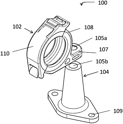
1. A clamp comprising:
a first clamp member having a substantially U-shaped clip with first and second arms connected at a distal end of the clip; and
a second clamp member having a housing comprising a channel arranged to receive the clip,
wherein:
the first clamp member is separable from and pivotably attached to the second clamp member;
the second clamp member is in a same plane as and cooperating with the first clamp member to define an opening through which a bundle of wires is insertable;
the housing further comprises a portion defining a floor of the channel;
the housing further comprises a portion defining a top of the channel;
a proximal end of the first arm of the clip comprises a feature arranged to engage with the top to hold the clip in the channel;
a portion of the first arm of the clip between the feature and the distal end of the clip on a side of the first arm facing away from the floor is concave; and
the floor comprises a flat portion adjacent the distal end of the clip.
|