| CPC C25B 9/19 (2021.01) [C25B 1/04 (2013.01); C25B 1/50 (2021.01); C25B 9/05 (2021.01); C25B 13/05 (2021.01); C25B 15/02 (2013.01); B01D 53/326 (2013.01); B01D 2256/16 (2013.01)] | 9 Claims |

|
1. A compression apparatus comprising:
an electrolyte membrane;
an anode disposed on a principal surface of the electrolyte membrane;
a cathode disposed on another principal surface of the electrolyte membrane;
an anode separator disposed on the anode;
a cathode separator disposed on the cathode;
a frame body arranged to surround an outer periphery of the electrolyte membrane; and
a voltage applicator that applies a voltage between the anode and the cathode,
wherein, upon the voltage applicator applying the voltage, the compression apparatus causes protons extracted from an anode fluid fed to the anode to migrate to the cathode through the electrolyte membrane and produces compressed hydrogen,
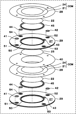
wherein the cathode separator has a first O-ring groove formed in a cathode-side principal surface of the cathode separator, the cathode-side principal surface being directed toward the cathode, so as to surround a region of the cathode-side principal surface, the region facing the cathode,
wherein the compression apparatus comprises a first O-ring held by the first O-ring groove and a face seal disposed on an outer periphery of a region of an anode-side principal surface of the anode separator, the anode-side principal surface being directed toward the anode, the region facing the anode, and
wherein the face seal is arranged to face a region of the anode-side principal surface of the electrolyte membrane, the anode-side principal surface of the electrolyte membrane being directed toward the anode, the region in which the anode is not disposed, and the face seal is arranged to face an anode-side principal surface of the frame body, the anode-side principal surface of the frame body being directed toward the anode.
|