| CPC B60K 15/035 (2013.01) [F16K 17/12 (2013.01); F16K 24/044 (2013.01); B60K 2015/03289 (2013.01); G05D 16/12 (2013.01); Y10T 137/0874 (2015.04)] | 6 Claims |

|
1. A valve device comprising:
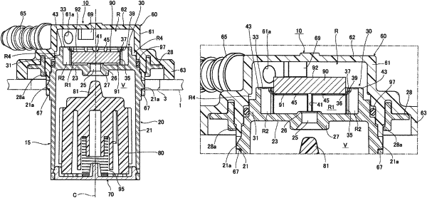
a housing in which a valve chamber is provided on a lower side and a ventilation chamber is provided on an upper side via a partition wall, the valve chamber communicating with an inside of a fuel tank, the ventilation chamber communicating with an outside of the fuel tank, and the partition wall being formed with a valve hole through which the valve chamber and the ventilation chamber communicate with each other;
a float valve accommodated in the valve chamber so as to be movable up and down and configured to open and close the valve hole; and
a pressure adjusting valve configured to adjust pressure and accommodated in the ventilation chamber so as to be movable up and down,
wherein a first valve seat which the pressure adjusting valve is configured to come into contact with and separate from is formed from the valve hole toward the upper side, and a second valve seat which the float valve is configured to come into contact with and separate from is formed from the valve hole toward the lower side,
wherein an accommodation portion configured to surround and accommodate the pressure adjusting valve is provided in a protruding manner from a surface of the partition wall toward the upper side, and an internal space of the accommodation portion communicates with the valve hole,
wherein an inner periphery of the accommodation portion is provided with
a reduced diameter portion positioned on a side of the partition wall, the reduced diameter portion having a shape surrounding an outer periphery of the pressure adjusting valve, and
an increased diameter portion positioned above the reduced diameter portion in an axial direction, the increased diameter portion having a shape larger in diameter than the outer periphery of the pressure adjusting valve,
wherein a height of an upper end of the reduced diameter portion from the surface of the partition wall on the side of the ventilation chamber is equal to or greater than a position of a front surface of the pressure adjusting valve in the axial direction when a back surface of the pressure adjusting valve is in contact with the first valve seat, and
wherein the front surface of the pressure adjusting valve and the back surface of the pressure adjusting valve are each positioned above the height of the upper end of the reduced diameter portion in the axial direction when the pressure adjusting valve is raised to a maximum due to an increase in pressure in the fuel tank.
|