| CPC B21B 13/02 (2013.01) | 17 Claims |

|
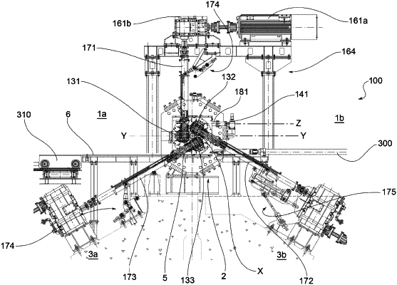
1. A rolling mill for solid elongated products, defining a rolling axis, comprising a first plurality of rolling stations and a second plurality of rolling stations placed in series along the rolling axis alternated with each other between an input and an output of the rolling mill, wherein each of said rolling stations comprises:
a load-bearing structure;
a roll-holder cartridge removably connected to the load-bearing structure in an extraction direction and comprising three rolling rolls mounted on the roll-holder cartridge to be radially mobile with respect to the rolling axis, the three rolls being rotatable around three respective axes of rotation placed at 120° from each other, one of said rolls having the respective axis of rotation arranged vertically and the other two of said rolls having their respective axes of rotation inclined with respect to vertical;
a system for synchronized mechanical adjustment of all three rolls mounted on board the roll-holder cartridge and operable, in use, to act on said rolls to maintain a predefined radial distance of the rolls from the rolling axis;
an actuator for actuating the synchronized mechanical adjustment system, the actuator being mounted on the load-bearing structure of the roll-holder cartridge;
a coupling body connected to the actuator and a kinematic connection element mechanically synchronized with the three rolls, the coupling body and the actuator rotating about an axis extending along a coupling direction and being configured to engage by coupling the synchronized mechanical adjustment system along the coupling direction;
three gear motor groups connected to the rolls by single extensions to provide the rolls with rotation and torque necessary to force a product to advance along the rolling axis;
wherein a position of the rolls of said second plurality of stations is rotated by 60° around the rolling axis with respect to a position of the rolls of said first plurality of stations so that the rolls with a vertical axis of the first plurality of stations are arranged on a first side of the rolling mill and the rolls with a vertical axis of the second plurality of stations are arranged on a second side of the rolling mill, opposite the first side with respect to the rolling axis;
wherein all the rolling stations of said rolling mill are configured to allow lateral extraction of the respective roll-holder cartridges from a same side of the rolling mill, corresponding either to said first side or to said second side;
wherein all the rolling stations have respective actuators for actuating the synchronized mechanical adjustment system either mounted in a fixed manner on the load-bearing structure of the roll-holder cartridge if the respective actuators are positioned on the side of the rolling mill opposite the cartridge extraction side and have the coupling direction parallel to the extraction direction, or
movably mounted on the load-bearing structure of the roll-holder cartridge if the respective actuators are positioned with the coupling direction intersecting the extraction direction, said respective actuators being movable in order to disengage the respective synchronized mechanical adjustment systems and release the cartridge extraction path;
wherein the single extensions of all the rolling stations are movable with respect to the load-bearing structures in order to disengage the respective rolls and free the cartridge extraction path.
|