| CPC A61B 17/320758 (2013.01) [A61B 2017/00057 (2013.01); A61B 2017/00075 (2013.01); A61B 2017/00553 (2013.01); A61B 2017/00557 (2013.01); A61B 2017/00778 (2013.01); A61B 2017/22069 (2013.01); A61B 2017/320004 (2013.01); A61B 2017/320008 (2013.01); A61B 2017/320766 (2013.01)] | 19 Claims |

|
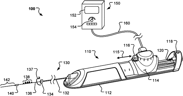
1. A rotational atherectomy apparatus comprising:
a torque-transmitting coil slidably and rotatably disposed within a lumen of a sheath such that at least one eccentric diamond-coated element fixedly mounted to a distal end portion of the torque-transmitting coil is positioned distally of a distal end of the sheath; and
a rotational atherectomy control handle attached to a proximal end of the sheath and configured to control rotation of the torque-transmitting coil, including:
a handle housing having a front housing portion coupled to a proximal end of the sheath and a rear housing portion, the handle housing containing a slidable carriage that is coupled with the torque-transmitting coil, the slidable carriage being slidably translatable in a longitudinal direction relative to both the front housing portion of the handle housing and the proximal end of the sheath so as to longitudinally translate the torque-transmitting coil relative to the front housing portion of the handle housing;
a rotation control button configured to activate rotation of the torque-transmitting coil and being carried by the slidable carriage so that the rotation control button is accessible along an upper side of the handle housing;
a carriage lock actuator that is movable relative to the handle housing and is configured to releasably lock the slidable carriage in a locked position that prevents translation of the slidable carriage in the longitudinal direction;
a guidewire access port positioned at a rear end the handle housing and axially aligned with the torque-transmitting coil and the lumen of the sheath; and
a fluid delivery port extending from the front housing portion of the handle housing at a location spaced apart distally from the slidable carriage, wherein the fluid delivery port is configured to provide fluid into the lumen of the sheath,
wherein the rotation control button is mounted to the slidable carriage such that both the rotation control button and the slidable carriage are simultaneously translatable in the longitudinal direction while the torque-transmitting coil is activated to rotate within the lumen of the sheath.
|