| CPC A61B 17/320758 (2013.01) [A61B 17/320725 (2013.01); A61B 2017/320004 (2013.01); A61B 2017/320733 (2013.01); A61B 2017/320741 (2013.01); A61B 2017/320766 (2013.01)] | 16 Claims |
|
1. A rotational atherectomy device, comprising:
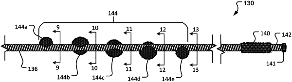
an elongate flexible drive shaft defining a longitudinal axis and comprising a torque-transmitting coil helically wound around the longitudinal axis in a first spiral direction extending toward a distal end of the elongate flexible drive shaft;
a spiraled set of three or more abrasive spheres fixedly mounted to the torque-transmitting coil such that each of the abrasive spheres has a center of mass offset from the longitudinal axis of the drive shaft at a radial angle different from each adjacent abrasive sphere of the spiraled set to thereby define a spiral path in which the centers of mass of the abrasive spheres around the longitudinal axis in a second spiral direction extending toward the distal end that is opposite of the first spiral direction;
an actuator handle assembly connected to the drive shaft and including a motor that drives rotation of the drive shaft about the longitudinal axis in the first spiral direction while the spiraled set of three or more abrasive spheres are fixedly mounted to the torque-transmitting coil along the spiral path in the second spiral direction that is opposite of the first spiral direction; and
an abrasive-coated metallic concentric element fixedly mounted to the torque-transmitting coil at a position distally spaced apart from a distal-most abrasive sphere of the spiraled set such that a center of mass of the abrasive-coated metallic concentric element is aligned with the longitudinal axis while each abrasive sphere in the spiraled set has its respective center of mass offset from the longitudinal axis.
|