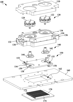
| CPC H05K 7/20272 (2013.01) [B23K 31/02 (2013.01); F28D 15/0233 (2013.01); F28D 15/046 (2013.01); F28F 9/18 (2013.01); H05K 7/20263 (2013.01); H05K 7/20336 (2013.01); H05K 7/2039 (2013.01); B23K 2101/14 (2018.08); F28F 2230/00 (2013.01); F28F 2245/00 (2013.01); F28F 2275/062 (2013.01); G06F 1/20 (2013.01)] | 13 Claims |

|
1. A liquid cooling head, comprising:
a bottom plate having an opening;
a heat dissipation plate fixed to the bottom plate;
a partition plate fixed on the bottom plate to divide the opening into a plurality of cooling chambers;
an upper cover plate fixed on the bottom plate; and
a plurality of guiding blades formed under the partition plate to guide a cooling liquid;
wherein each of the cooling chambers is respectively equipped with a cooling liquid inlet formed in the upper cover plate, a cooling liquid outlet formed in the upper cover plate, a pump arranged between the partition plate and the upper cover plate, and an electric control device rotating a corresponding pump to force the cooling liquid to flow through a corresponding chamber of the cooling chambers to cool at least one heat source below the heat dissipation plate;
wherein the partition plate comprises a horizontal baffle and a vertical baffle, the vertical baffle is connected to the horizontal baffle, and the vertical baffle divides the opening into the cooling chambers respectively located on both sides of the vertical baffle, an included angle is formed between the guiding blades and the vertical baffle to guide the cooling liquid flowing toward the vertical baffle, and an interval between two adjacent guiding blades close to the vertical baffle is gradually larger than an interval between two adjacent guiding blades far away from the vertical baffle.
|
|
8. A liquid cooling device, comprising:
a liquid cooling head, wherein the liquid cooling head comprises:
a bottom plate having an opening;
a heat dissipation plate fixed to the bottom plate;
a partition plate fixed on the bottom plate to divide the opening into a plurality of cooling chambers;
an upper cover plate fixed on the bottom plate; and
a plurality of guiding blades formed under the partition plate to guide a cooling liquid;
wherein each of the cooling chambers is respectively equipped with a cooling liquid inlet formed in the upper cover plate, a cooling liquid outlet formed in the upper cover plate, a pump arranged between the partition plate and the upper cover plate, and an electric control device rotating a corresponding pump to force the cooling liquid to flow through a corresponding chamber of the cooling chambers to cool at least one heat source below the heat dissipation plate;
wherein the partition plate comprises a horizontal baffle and a vertical baffle, the vertical baffle is connected to the horizontal baffle, and the vertical baffle divides the opening into the cooling chambers respectively located on both sides of the vertical baffle, an included angle is formed between the guiding blades and the vertical baffle to guide the cooling liquid flowing toward the vertical baffle, and an interval between two adjacent guiding blades close to the vertical baffle is gradually larger than an interval between two adjacent guiding blades far away from the vertical baffle;
wherein the cooling chambers comprises a first cooling chamber and a second cooling chamber; and
a first cooling tower, wherein the first cooling tower comprises a first liquid entrance opening and a first liquid exit opening, wherein the first liquid entrance opening is connected to the cooling liquid outlet of the second cooling chamber, and the first liquid exit opening is connected to the cooling liquid inlet of the first cooling chamber to allow the cooling liquid from the second cooling chamber entering into the first cooling tower to dissipate heat and then entering into the first cooling chamber.
|