| CPC H05B 6/6408 (2013.01) [A47J 37/0629 (2013.01); A47J 37/0664 (2013.01)] | 10 Claims |

|
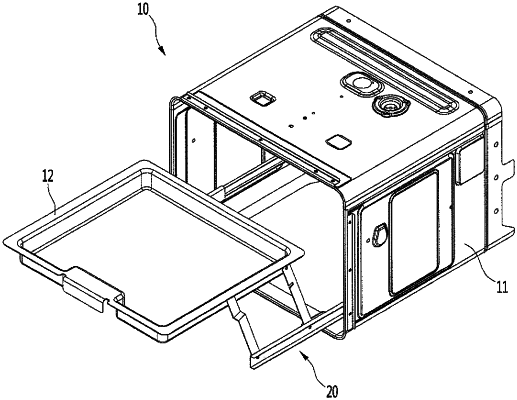
1. A cooking apparatus, comprising:
a cabinet having a cooking space therein;
a tray on a top surface of which an object to be cooked is placed; and
a pair of elevation devices configured to connect side surfaces of an inside of the cabinet to side surfaces of the tray, the pair of elevation devices being configured so that the tray is insertable into and withdrawable from the cooking space, wherein each of the elevation device comprises:
a fixed rail fixed to one of the side surfaces of the cabinet;
a movable rail configured to move in frontward and rearward directions along the fixed rail in a state of being connected to the fixed rail;
an arm member having a first end rotatably connected to an outer surface of the movable rail and a second end connected to one of the side surfaces of the tray to elevate the tray, wherein the arm member comprises a front arm and a rear arm, which are spaced apart from each other in the frontward and rearward directions;
a latch unit disposed on an inner surface of the movable rail and configured to restrict movement of the movable rail when the arm member rotates to elevate the tray; and
an elastic member interposed between the latch unit and the inner surface of the movable rail, wherein the latch unit is mounted on the inner surface of the movable rail facing a side surface of the fixed rail and includes a latch, wherein the movable rail comprises:
an upper hole into which a first end of the latch is inserted; and
a lower hole into which a second end of the latch is inserted, wherein, when the arm member is not rotated, the lower hole is covered by the rear arm, and when the rear arm is rotated to open the lower hole, the latch is rotated by a restoring force of the elastic member, and the first end of the latch is moved out of the upper hole by the rotation of the latch.
|