| CPC H05B 45/40 (2020.01) [H03K 7/08 (2013.01); H05B 47/19 (2020.01); H05B 45/20 (2020.01)] | 23 Claims |

|
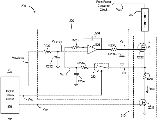
1. A drive circuit for a light-emitting diode (LED) light source, comprising:
a controllable impedance circuit configured to conduct a load current through the LED light source;
a first switching device connected in series with the controllable impedance circuit and responsive to a pulse-width modulated (PWM) signal;
a feedback circuit configured to generate a feedback signal indicative of a magnitude of the load current conducted through the LED light source;
a control loop circuit coupled to the feedback circuit and configured to generate a drive signal for controlling the controllable impedance circuit in response to a target-current control signal and the feedback signal, the control loop circuit comprising a second switching device, the second switching device capable of being rendered conductive and non-conductive in response to a switch control signal to control when the feedback signal is used to generate the drive signal, the control loop circuit configured to adjust a peak magnitude of the load current conducted through the LED light source toward a target magnitude based on the target-current control signal;
wherein the first switching device is rendered conductive and non-conductive in response to the PWM signal and a duty cycle of the PWM signal is adjusted to adjust an average magnitude of the load current, and wherein the second switching device is rendered conductive and non-conductive in response to the switch control signal in coordination with the PWM signal.
|