| CPC H04R 9/06 (2013.01) [H04R 1/026 (2013.01); H04R 3/00 (2013.01); H04R 9/045 (2013.01)] | 19 Claims |

|
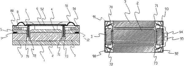
1. A sound generating unit, comprising a magnetic circuit system, a vibration system, and a circuit board, wherein the magnetic circuit system comprises a magnetic yoke, a central magnetic circuit portion and a side magnetic circuit portion each arranged on the magnetic yoke; wherein at least one of the central magnetic circuit portion and the side magnetic circuit portion comprises a permanent magnet, and the central magnetic circuit portion and the side magnetic circuit portion form a magnetic gap therebetween; wherein the vibration system comprises a diaphragm and a voice coil connected with a first end thereof to the diaphragm and extending with a second end thereof into the magnetic gap of the magnetic circuit system;
wherein, the voice coil includes two voice coil wires wound together, and each voice coil wire having a wire-in end and a wire-out end; the voice coil having on a first side thereof lead-out positions of two wire-in ends, and on a second side thereof lead-out positions of two wire-out ends; the two wire-in ends and the two wire-out ends being respectively electrically connected to corresponding pads of the circuit board, and the circuit board having an internal circuit configured to electrically connect the two wire-in ends together and to electrically connect the two wire-out ends together;
the side magnetic circuit portion is formed with an accommodating groove at a side away from the magnetic gap, and the circuit board is of a hollow ring shape and is arranged in the accommodating groove.
|