| CPC H02M 7/538466 (2013.01) [H02M 1/08 (2013.01); H02M 7/4815 (2021.05)] | 3 Claims |

|
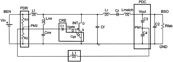
1. A power converter for converting a DC input voltage (Vin) into an AC output voltage (Vout), the power converter having a structure of Phi-2 type, and comprising:
an input terminal (BEN) for the DC input voltage (Vin),
an output terminal (BSO) for the AC output voltage (Vout),
a power switch (INT) equipped with a control electrode (G), a first electrode (D) and a second electrode (S) linked to a reference potential (GND),
wherein the converter further comprises a self-oscillating circuit, connected between the output terminal (BSO) and the control electrode (G), and configured to supply and maintain a sinusoidal drive signal to the control electrode of the power switch (INT) from the output voltage,
the self-oscillating circuit comprising a capacitive divider bridge (PDC) connected between the output terminal (BSO) and the reference potential (GND), and further comprising a first inductor (L1) connected on a first side to a first midpoint (PM1) of the capacitive divider bridge (PDC) and on a second side to the control electrode (G) via a reactive circuit (CRE),
the reactive circuit (CRE) comprising at least one series resonant circuit (CRS1, CRS2), connected between the control electrode (G) and the reference potential (GND), and the resonance frequency of which is equal to a corresponding harmonic frequency of the drive signal.
|