| CPC H02M 3/158 (2013.01) [G01R 19/16538 (2013.01); H03K 5/24 (2013.01); H02M 1/0012 (2021.05); H02M 1/0025 (2021.05)] | 20 Claims |
|
13. A controller including:
(a) a DC-to-DC converter circuit having an input for receiving an input voltage, and an output for outputting an output voltage different from the input voltage in response to a pulse-width modulated (PWM) control signal;
(b) a PWM duty cycle controller coupled to the DC-to-DC converter circuit and configured to generate the PWM control signal to the DC-to-DC converter circuit from an M-bit count value;
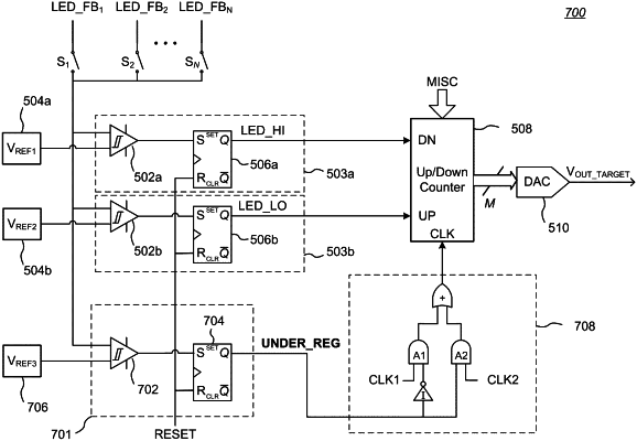
(c) a counter having a clock signal input, an increment input for receiving an increment control signal based on at least one feedback voltage from a load powered by a signal output by the power converter, a decrement input for receiving a decrement control signal based on the at least one feedback voltage, an under-shoot input, an over-shoot input, and an output providing the M-bit count value;
(d) a digital-to-analog converter coupled to the output of the counter and to the PWM duty cycle controller, the digital-to-analog converter configured to output to the PWM duty cycle controller a signal corresponding to the provided M-bit count value from the counter;
(e) a first comparator including an output coupled to the under-shoot input of the counter, a first input coupled to the digital-to-analog converter, and a second input configured to be coupled to a signal representative of an output voltage of the power converter, the first comparator outputting a first control signal indicating an under-shoot condition if the difference between the first input and second input of the first comparator exceeds a first offset value; and
(f) a second comparator including an output coupled to the over-shoot input of the counter, a first input coupled to the digital-to-analog converter, and a second input configured to be coupled to a signal representative of an output voltage of the power converter, the second comparator outputting a second control signal indicating an over-shoot condition if the difference between the first input and second input of the second comparator exceeds a second offset value;
wherein receipt of the first control signal or the second control signal causes the counter to limit the range of values for the M-bit count value to mitigate the corresponding under-shoot condition or over-shoot condition.
|