| CPC G02F 1/294 (2021.01) [G02B 6/003 (2013.01); G02B 6/0031 (2013.01); G02B 27/0093 (2013.01); G02F 1/0136 (2013.01); G06F 3/013 (2013.01); G06V 10/25 (2022.01); H04N 9/317 (2013.01); G02F 1/133524 (2013.01); G02F 1/133526 (2013.01); H04N 9/3161 (2013.01)] | 17 Claims |

|
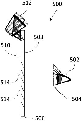
1. A display system for displaying an image to an eye of a user, the eye being located within an eye motion box, the display system comprising:
(a) a light-guide optical element (LOE) having a pair of major external surfaces that are parallel;
(b) an image projector projecting image illumination of a collimated image, said image projector being optically coupled to said LOE so as to introduce said image illumination into said LOE so as to propagate within said LOE by internal reflection at said pair of major external surfaces, said image projector including an electrically-controllable variable lens;
(c) a coupling-out configuration associated with at least a coupling-out region of said LOE, said coupling-out configuration being configured to redirect at least part of said image illumination propagating within said LOE towards the eye motion box for viewing by the eye of the user; and
(d) a controller comprising at least one processor, said controller associated with said electrically-controllable variable lens and configured to:
(i) determine a current region of interest of the image, and
(ii) generate an actuation signal to vary a property of said electrically-controllable variable lens so as to reduce at least one type of aberration in the current region of interest of the image as viewed by the eye of the user at the expense of increased aberration in at least one area of the image outside the current region of interest.
|