| CPC G02B 6/428 (2013.01) [G02B 6/4204 (2013.01); G02B 6/43 (2013.01)] | 19 Claims |

|
1. An optical module, comprising:
a shell;
a circuit board located in the shell;
a light-emitting chip disposed on the circuit board and configured to convert an electrical signal from the circuit board into an optical signal;
a lens assembly disposed on the circuit board, covering the light-emitting chip, and being configured to change a propagation direction of the optical signal transmitted into the lens assembly;
a first optical fiber ribbon; an end of the first optical fiber ribbon being optically connected to the lens assembly, and another end of that being optically connected to an optical fiber socket; the first optical fiber ribbon being configured to transmit the optical signal to the optical fiber socket; and
an optical fiber holder configured to fix an end of the first optical fiber ribbon that is connected to the lens assembly; the optical fiber holder being connected to the lens assembly;
wherein the lens assembly includes:
a lens base disposed on the circuit board, covering the light-emitting chip, and being configured to change the propagation direction of the optical signal transmitted into the lens assembly;
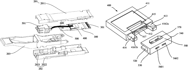
a first positioning column disposed on a side of a first assembly surface of the lens base and extending toward the optical fiber holder; and
a second positioning column disposed on another side of the first assembly surface and extending toward the optical fiber holder;
wherein the first assembly surface is a surface of the lens base opposite to the optical fiber holder;
wherein the optical fiber holder includes:
a first positioning hole disposed on a second assembly surface of the optical fiber holder, corresponding to a position of the first positioning column, and being configured to allow the first positioning column to be inserted; the first positioning hole having an opening on the second assembly surface and an opening on a first side surface of the optical fiber holder connected to the second assembly surface respectively, and two openings of the first positioning hole being connected; and
a second positioning hole disposed on the second assembly surface, corresponding to a position of the second positioning column, and being configured to allow the second positioning column to be inserted; the second positioning hole having an opening on the second assembly surface and an opening on a second side surface of the optical fiber holder connected to the second assembly surface respectively, and two openings of the second positioning hole being connected;
wherein the second assembly surface is a surface of the optical fiber holder opposite to the lens base.
|