| CPC F25B 49/022 (2013.01) [F25B 7/00 (2013.01); F25B 9/008 (2013.01); F25B 30/02 (2013.01); F25B 39/00 (2013.01); F25B 41/20 (2021.01); F25B 41/345 (2021.01); F25B 47/022 (2013.01); F25B 2600/2501 (2013.01); F25B 2600/2513 (2013.01); F25B 2700/197 (2013.01); F25B 2700/21172 (2013.01); F25B 2700/21174 (2013.01); F25B 2700/21175 (2013.01)] | 10 Claims |

|
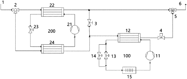
1. A precooler-based transcritical CO2 heat pump system, comprising: a circulating waterway system, a CO2 heat pump system and a precooler system;
wherein the circulating waterway system comprises: a system water inlet (1), a three-way diversion valve (2), a waterway two-way regulating valve (4), a three-way confluence valve (5) and a system water outlet (6);
the CO2 heat pump system comprises: a CO2 compressor (11), a CO2 gas cooler (12), an electronic expansion valve (13), a defrosting solenoid valve (14) and a CO2 evaporator (15);
the precooler system comprises: a precooling system compressor (21), a precooling system condenser (22), a thermal expansion valve (23) and a precooling system evaporator (24);
in the circulating waterway system, the system water inlet (1) is connected to an inlet of the three-way diversion valve (2), and system inlet water is divided into two parts through the three-way diversion valve (2): a first outlet of the three-way diversion valve is connected to a first inlet of the precooling system condenser (22) and then connected to a first inlet of the three-way confluence valve (5); a second outlet of the three-way diversion valve is connected to a first inlet of the precooling system evaporator (24), then connected to a first inlet of the CO2 gas cooler (12) of the CO2 heat pump system, then connected to the waterway two-way regulating valve (4), and then connected to a second inlet of the three-way confluence valve (5); and an outlet of the three-way confluence valve (5) is connected to the system water outlet (6); an outlet of the precooling system compressor (21) in the precooler system is connected to a second inlet of the precooling system condenser (22), a second outlet of the precooling system condenser (22) is connected to an inlet of the thermal expansion valve (23), an outlet of the thermal expansion valve (23) is connected to a second inlet of the precooling system evaporator (24), and a second outlet of the precooling system evaporator (24) is connected to an inlet of the precooling system compressor (21), in such a manner that a circulation loop is formed;
an outlet of the CO2 compressor (11) in the CO2 heat pump system is connected to a second inlet of the CO2 gas cooler (12), a second outlet of the CO2 gas cooler (12) is connected to an inlet of the electronic expansion valve (13), an outlet of the electronic expansion valve (13) is connected to an inlet of the CO2 evaporator (15), and an outlet of the CO2 evaporator (15) is connected to an inlet of the CO2 compressor (11); and a refrigerant pipeline of an outlet of the CO2 gas cooler (12) is also short-circuited to the inlet of the CO2 evaporator (15) through the defrosting solenoid valve (14).
|