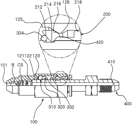
| CPC F16L 37/22 (2013.01) [F16L 37/47 (2013.01)] | 2 Claims |

|
1. One-touch high-pressure fluid fitting using a spring, the one-touch high-pressure fluid fitting comprising:
a fitting body formed with an inlet and an insertion hole and having a hollow portion;
a fitting cap coupled to the fitting body, and including a cut piece having one end formed with an inward inclined surface;
a support member positioned in the hollow portion to support the inward inclined surface of the fitting cap; and
an insertion tube inserted into the hollow portion of the fitting body and fastened to or unfastened from the fitting cap,
wherein the hollow portion includes a check valve seating hollow part, an insertion tube seating hollow part, a support member seating hollow part, a cut piece expansion hollow part, and an inclined hollow part, along a longitudinal direction from the inlet to the insertion hole,
wherein the fitting body includes an inner wall, and the inner wall includes an insertion tube seating inclined wall, an insertion tube seating side wall, a support member fixing surface, a support member seating side wall, an insertion tube extension side wall, and a double inclined protrusion wall, along the longitudinal direction from the inlet to the insertion hole,
wherein inclined surfaces are formed on both sides of the double inclined protrusion wall along the longitudinal direction from the inlet to the insertion hole,
wherein a predetermined section of a protruding end of the double inclined protrusion wall is parallel to the insertion tube seating side wall, the support member seating side wall and the insertion tube extension side wall,
wherein the support member includes a sealing ring mounted on the hollow portion of the fitting body, a flat ring coming into contact with the sealing ring, and a spring coming into contact with the flat ring to elastically support the inward inclined surface of the fitting cap,
wherein the cut piece includes an outward inclined surface which is formed on a side opposite to the inward inclined surface of the fitting cap,
wherein the spring elastically supports the inward inclined surface of the fitting cap, when the fitting cap is fastened to the fitting body, so that the outward inclined surface formed on the cut piece is positioned in contact with one inclined surface of the double inclined protrusion wall,
wherein the spring is formed with a first flat part and a second flat part at both ends thereof in the longitudinal direction,
wherein the first flat part comes into contact with the flat ring, and the second flat part comes into contact with the inward inclined surface formed on the cut piece of the fitting cap,
wherein the spring presses the flat ring through the first flat part, and transfers an elastic force to the inward inclined surface formed on the cut piece of the fitting cap through the second flat part,
wherein the cut piece of the fitting cap is formed with a locking protrusion part adjacent to the inward inclined surface, and the insertion tube is formed therein with a locking groove, so that the locking protrusion part and the locking groove are fastened or unfastened with each other,
wherein when the insertion tube is fastened to the fitting body, the inward inclined surface of the fitting cap is pressed against the second flat part of the spring outwardly in order for the cut piece of the fitting cap to expand outward into the insertion tube extension side wall, until the locking protrusion part of the fitting cap is received in the locking groove of the insertion tube and the second flat part of the spring pushes outward against the inward inclined surface of the fitting cap to make the outward inclined surface of the fitting cap be in contact with and be resisted by the one inclined surface of the double inclined protrusion wall, and
wherein when the fitting cap is pressed toward the fitting body to unfasten the insertion tube from the fitting body, the inward inclined surface of the fitting cap presses the second flat part of the spring in order for the cut piece of the fitting cap to expand outward, until the locking protrusion part of the fitting cap releases from the locking groove of the insertion tube to facilitate unfastening of the insertion tube out of the fitting body.
|