| CPC F04B 53/144 (2013.01) [F04B 19/22 (2013.01); F04B 53/147 (2013.01); F04B 53/162 (2013.01); F04B 53/22 (2013.01); F15B 15/1438 (2013.01); F04B 15/02 (2013.01)] | 14 Claims |

|
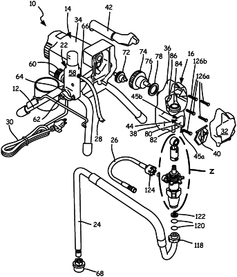
1. A method of mounting and dismounting a pump from a drive housing and a driving link, the drive housing having a mounting slot with a forward facing opening through a front of the drive housing, the drive housing further having a bottom and a lower opening extending through the bottom of the drive housing, the driving link located within drive housing, the driving link comprising a drive cavity, the pump comprising a pump cylinder having a top end, the pump further comprising a first ring projecting from the pump cylinder and a second ring projecting from the pump cylinder such that a gap is formed between the first ring and the second ring, and the pump further comprising a pump rod that extends out from the top end of the pump cylinder, the pump rod comprising a head connected to a neck, the head wider than the neck, wherein the method comprises:
mounting the pump to the drive housing by inserting the pump into the mounting slot through the forward facing opening of the drive housing such that the drive housing is received within the gap between the first ring and the second ring and that the head slides into the drive cavity of the driving link;
operating the pump while the pump extends from within the mounting slot down through the lower opening and the neck of the pump rod extends down through the driving link while the head is held by the driving link, and the first ring is disposed within the mounting slot to support the pump while the second ring is disposed outside of the mounting slot and in engagement with the bottom of the drive housing;
removing the pump from the drive housing by sliding the pump out from the mounting slot of the drive housing through the forward facing opening such that the drive housing slides out from the gap and the head slides out from the drive cavity.
|
|
14. A method of mounting and dismounting a pump from a drive housing and a driving link, the drive housing having a bottom, the drive housing having a lower opening extending through the bottom of the drive housing and open to a cavity in the drive housing, and the drive housing having a forward facing opening open to the cavity, the driving link located within the drive housing, the driving link comprising a drive cavity, the pump comprising a cylinder comprising a top end, the pump further comprising a first ring projecting from the cylinder and a second ring projecting from the cylinder, and the pump further comprising a pump rod that extends out from the top end of the cylinder, the pump rod comprising a head connected to a neck, the head wider than the neck, wherein the method comprises:
securing the pump to the drive housing such that the pump hangs down from the drive housing by:
moving the pump through the forward facing opening and into the cavity such that the pump is at least partially disposed in the cavity and the pump hangs down through the lower opening, and such that the head of the pump rod extends within the drive housing;
sliding the head laterally into the drive cavity so that the neck extends downward through the driving link; and
sliding the pump cylinder laterally such that a flange of the drive housing is received in a gap formed between the first ring and the second ring; and
removing the pump from the drive housing by:
sliding the pump cylinder laterally such that the flange of the drive housing is withdrawn from the gap;
sliding the head laterally out of the drive cavity; and
withdrawing the pump rod from the drive housing.
|