|
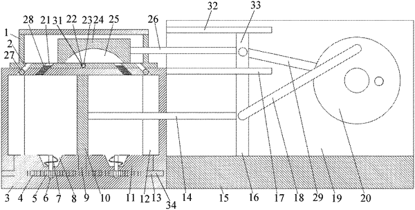
1. An apparatus for removing ammonia nitrogen from electrolytic manganese residue, comprising a treatment tank, an overflow tank, a stirring component and an adjusting component, wherein the overflow tank is connected to a top of the treatment tank, and a tank bottom of the overflow tank is attached to a surface of the treatment tank, a bottom of the overflow tank and the top of the treatment tank are both provided with two groups of guiding holes, the two groups of guiding holes are adjacent to opposite side walls of the overflow tank and the treatment tank, and corresponding guiding holes on a same side of the overflow tank and the treatment tank are communicated, a lower surface of the treatment tank is provided with a limiting groove and grooves, a chute is arranged in a wall of the treatment tank along a length direction thereof, one end of the chute penetrates through the wall of the treatment tank, and the chute is located right below the limiting groove; the adjusting component comprises a partition plate and a driving component driving the partition plate to reciprocate in the treatment tank, the partition plate is vertically arranged and divides the treatment tank into two portions, and the guiding holes on the treatment tank are located in a movement direction of the partition plate, the stirring component comprises stirring rods and racks, the racks are slidably connected in the chute, and the stirring rods are rotatably connected in the wall of the treatment tank, two ends of the stirring rods are respectively provided with gears and stirring blades, the stirring blades are positioned in the grooves, and the gears are meshed with the racks, a bottom of the partition plate is fixedly connected with a connecting rod, and the connecting rod is positioned in the limiting groove and fixedly connected with the racks; an outer wall of the treatment tank is fixedly connected with a base, a fixed plate is vertically and fixedly connected with the base, and a first limiting plate is fixedly connected with the fixed plate, the partition plate is fixedly connected with a first driving rod, the first driving rod extends out of the treatment tank, and one end of the first driving rod away from the partition plate is fixedly connected with a first sliding plate, the first sliding plate is connected between the first limiting plate and the base in a sliding way, the driving component comprises a first traction rod, a motor and a driving disk installed on the motor, and the first traction rod is in a shape of “]” character; two ends of the first traction rod are rotatably connected to an eccentric position of the driving disk and a side wall of the first sliding plate respectively; the overflow tank is internally connected with a sliding block in a sliding way, a bottom of the sliding block is provided with a drainage groove, the bottom of the overflow tank and the top of the treatment tank are both provided with two groups of drainage holes, the two groups of drainage holes are both located between the two groups of guiding holes, and corresponding drainage holes on a same side of the overflow tank and the treatment tank are communicated; a length of the drainage groove is smaller than a distance between the two groups of drainage holes, wherein one group of the drainage holes is communicated with the drainage groove, an inner bottom of the overflow tank is provided with a liquid outlet groove, an outer wall of the overflow tank is provided with a liquid outlet hole communicated with the liquid outlet groove, and the liquid outlet hole is connected with a screw rod by threads; the outer wall of the treatment tank is provided with connecting holes, the connecting holes are communicated with the guiding holes, and the connecting holes are internally connected with plugging rods for plugging the guiding holes by threads, the fixed plate is fixedly connected with a second limiting plate, the second limiting plate is positioned above the first limiting plate, and a second sliding plate is connected between the first limiting plate and the second limiting plate in a sliding way, the sliding block is fixedly connected with a second driving rod, and one end of the second driving rod away from the sliding block extends out of the overflow tank and is fixedly connected with the second sliding plate; the driving component also comprises a second traction rod, and the second traction rod is also in a shape of “]” character; two ends of the second traction rod are rotatably connected to an eccentric position of a driving disk and a side wall of the second sliding plate respectively; the first traction rod and the second traction rod are located at two sides of the driving disk respectively, and a distance between a joint of the second traction rod and the driving disk and a center of the driving disk is smaller than a distance between a joint of the first traction rod and the driving disk and the center of the driving disk.
|
