| CPC B66F 9/125 (2013.01) [B65D 19/0097 (2013.01); B65D 2519/00298 (2013.01); B65D 2519/00338 (2013.01); B65D 2519/00815 (2013.01)] | 16 Claims |

|
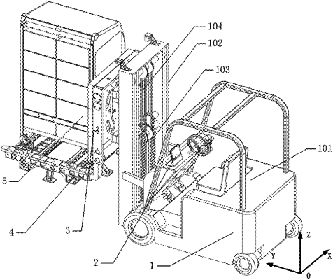
1. An assembly and test operation robot for a space station experimental cabinet, comprising a mobile lifting platform (1), a comprehensive monitoring system (2), a rotating clamping mechanism (3), a multifunctional adapter (4) and a science experimental cabinet (5), wherein:
the mobile lifting platform (1) is used for regulating a horizontal position and a height position of the science experimental cabinet (5) to realize assembly and transportation functions of the experimental cabinet;
the rotating clamping mechanism (3) is installed on the mobile lifting platform (1) to realize clamping and rotation functions of the science experimental cabinet (5);
the multifunctional adapter (4) is installed on the rotating clamping mechanism (3) to carry the science experimental cabinet (5);
the comprehensive monitoring system (2) is used to monitor an assembly state of the science experimental cabinet (5) in real time,
wherein the mobile lifting platform (1) comprises a waling mechanism (101) and a lifting mechanism,
wherein the lifting mechanism is arranged on a front end of the waling mechanism (101), and the rotating clamping mechanism (3) is arranged on the lifting mechanism,
wherein the lifting mechanism comprises a lifting support frame (102), a chain transmission mechanism (103) and a wire rope transmission mechanism (104), wherein the lifting support frame (102) is connected with the waling mechanism (101); the lifting support frame (102) is provided with a vertical orbit; the rotating clamping mechanism (3) is in sliding connection with the vertical orbit; the chain transmission mechanism (103) and the wire rope transmission mechanism (104) are respectively arranged on a lower end and an upper end of the lifting support frame (102); the wire rope transmission mechanism (104) and the chain transmission mechanism (103) are connected with the rotating clamping mechanism (3); the chain transmission mechanism (103) is used for driving winding and releasing of a wire rope in the wire rope transmission mechanism (104); and the wire rope transmission mechanism (104) is used for lifting the rotating clamping mechanism (3).
|