| CPC B64C 25/20 (2013.01) [B64C 25/001 (2013.01); B64C 25/12 (2013.01); B64C 25/62 (2013.01); B64C 2025/008 (2013.01); B64C 2025/125 (2013.01); B64C 2025/325 (2013.01)] | 20 Claims |

|
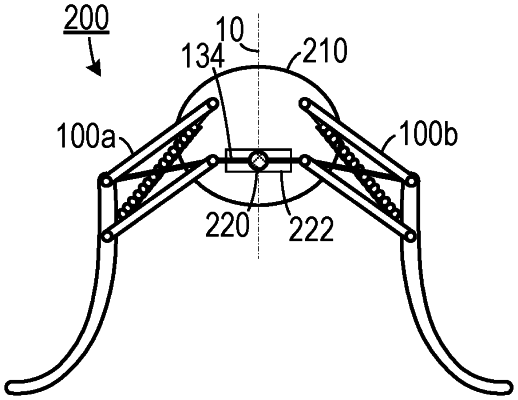
1. A two leg system, comprising:
(a) a first leg mechanism;
(b) a second leg mechanism, reflectively disposed oppositely from the first leg mechanism; and
(c) an actuator that applies tension to a continuous cable, wherein each of the first leg mechanism and the second leg mechanism comprise:
(i) a first platform coupling joint and a second platform coupling joint spaced apart from and disposed below the first platform coupling joint at a first distance;
(ii) a first lateral bar having a proximal end and an opposite distal end, the proximal end rotationally coupled to the first platform coupling joint so that the first lateral bar is rotatable about the first platform coupling joint and is constrained to movement along a predetermined plane;
(iii) a second lateral bar, disposed below the first lateral bar, having a proximal end and an opposite distal end, the proximal end rotationally coupled to the second platform coupling joint so that the second lateral bar is rotatable about the second platform coupling joint and is constrained to movement along the predetermined plane;
(iv) an upright bar that moves vertically in response to an amount of tension applied to the continuous cable including a first bar coupling joint and a second bar coupling joint spaced apart from the first bar coupling joint at the first distance, the distal end of the first lateral bar hingedly coupled to the first bar coupling joint and the distal end of the second lateral bar hingedly coupled to the second bar coupling joint so that the first lateral bar, the second lateral bar and the upright bar are constrained to movement along the predetermined plane;
(v) a passive device configured to apply force to the upright bar; and
(vi) the continuous cable being affixed adjacent to a selected one of the first bar coupling joint and the second bar coupling joint and engaging the second platform coupling joint when affixed adjacent to the first bar coupling joint or engaging the first platform coupling joint when affixed adjacent to the second bar coupling joint
wherein when the continuous cable is drawn away from the upright bar, the continuous cable applies inward force to the upright bar and the upright bar moves in a first direction,
and wherein when tension is released from the continuous cable, the passive device exerts a force on the upright bar that causes the upright bar to move in a second direction that is opposite the first direction.
|