| CPC B23P 11/025 (2013.01) | 7 Claims |

|
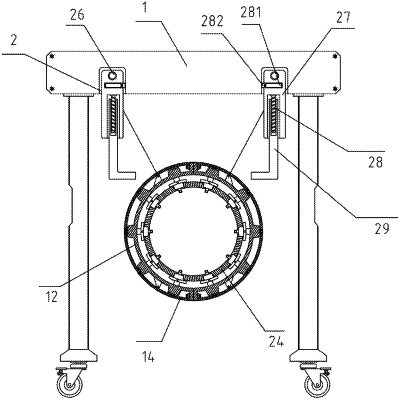
1. A rolling ring shrink fitting tool for rotary equipment, comprising a lifting frame (1),wherein a movement slot (2) is formed in a bottom surface of a top of the lifting frame (1); a lifting seat (3) is slidably mounted in the movement slot (2); a first motor (4) is fixedly embedded in the lifting seat (3); an output end of the first motor (4) is connected with a main gear (5); pinions (6) are engaged to two sides of the main gear (5); one end of each pinion (6) is connected with a wind-up roller (7); wire ropes (8) are wound on the wind-up rollers (7); guide rollers (9) are embedded in the lifting seat (3) through bearings; movable rollers (10) are elastically slidably embedded in a bottom of the lifting seat (3) through springs (11);
the rolling ring shrink fitting tool further comprises:
shrink fitting plates (12), wherein the shrink fitting plates (12) are two semicircular structures; protruding positions at tops of the two shrink fitting plates (12) are in fastened connection through bolts; lifting lugs (13) are welded on outer sides of the shrink fitting plates (12); one end of each wire rope (8) is fixed on the lifting lugs (13); the wire ropes (8) are wound on the guide rollers (9) and the movable rollers (10); tooth rings (14) are arranged outside the shrink fitting plates (12); the tooth rings (14) are two halves; stop rods (15) are fixed on inner walls of the tooth rings (14); one end of each stop rod (15) is located in a stop slot (16); the stop slots (16) are formed in outer sides of the shrink fitting plates (12);
supporting screw rods (17) are embedded at sunken positions on the inner walls of the shrink fitting plates (12) through bearings; outer ends of the supporting screw rods (17) are connected with bevel gears (18); the bevel gears (18) are located on the outer sides of the shrink fitting plates (12); positions of the shrink fitting plates (12) located on front and rear sides of the tooth rings (14) are engaged with the tooth rings (14); inner ends of the supporting screw rods (17) are sleeved with supporting seats (19) through threads; inner ends of the supporting seats (19) are fixed with supporting plates (20); stop plates (21) are fixed at top edges of the supporting plates (20); positioning plates (22) are fixed at inner ends of the stop plates (21) on the supporting plates (20) on a rear side; positioning rods (23) are welded on rear sides of the positioning plates (22); inner ends of the supporting plates (20) are fastened with a rolling ring body (24); and
a second motor (25), wherein the second motor (25) is fixed on a front end surface of the top of the lifting frame (1); an output end of the second motor (25) is connected with push screw rods (26); the push screw rods (26) are mounted in the movement slot (2) through bearings; smooth surfaces of rear ends of the push screw rods (26) penetrate in the lifting seat (3); front ends of the push screw rods (26) are sleeved with push seats (27) through threads; the push seats (27) abut against and slide in the movement slot (2); adjustment screw rods (28) are embedded in recesses in bottoms of the push seats (27); and push plates (29) sleeve the adjustment screw rods (28) through threads.
|