| CPC B21F 1/004 (2013.01) [A61C 7/02 (2013.01)] | 20 Claims |

|
1. A bending device comprising:
a providing part configured to provide a wire;
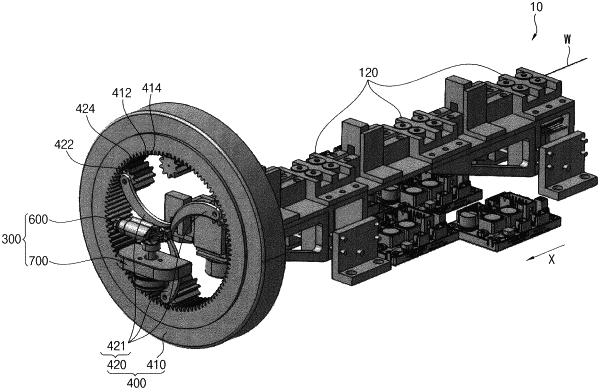
a bending unit disposed at a front side of the providing part, and comprising a fixing part and a bending part, the fixing part being configured to fix the wire, the bending part being configured to bend the wire fixed by the fixing part;
a cutting part configured to cut the wire bent by the bending part; and
a guide jig part having an upper jig and a lower jig opposite to the upper jig in a direction crossing a moving direction of the wire from the providing part toward the bending unit,
wherein
the bending part comprises a bending module, and the bending module is rotated along a circumferential direction or moves along a direction different from the circumferential direction to make contact with at least one side of the wire for bending the wire, and
each of the upper jig and the lower jig has a plate shape extending in the moving direction of the wire to sandwich the wire bent by the bending unit.
|