| CPC A47J 37/0731 (2013.01) [A47J 37/0704 (2013.01); A47J 37/0786 (2013.01)] | 6 Claims |
|
1. A stove comprising:
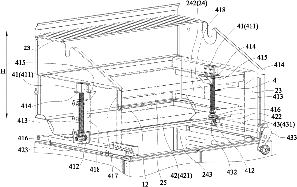
a base seat including a seat body and a drip pan;
a top seat disposed on top of said seat body, said top seat having a front wall, a rear wall, and two connecting walls that are spaced apart from each other and connected between said front wall and said rear wall, said front, rear and connecting walls cooperatively bounding a mounting space, said top seat further having a support rack that permits said drip pan to be disposed thereon and that divides said mounting space into an upper heating region and a lower transmission region located below said upper heating region;
a heating unit including a heater that extends into said heating region and that is located above said drip pan, and a heating seat that supports said heater;
an adjustment unit including
two lifting units respectively connected to said connecting walls of said top seat, each of said lifting units having
a screw rod extending in both of said heating region and said transmission region, a sliding block engaged with and driven by said screw rod to move upward or downward therealong, and a lift frame mounted onto said sliding block for concurrent movement therewith,
a synchronizer connecting said two lifting units, and
a drive unit connected to said screw rod of one of said lifting units and operable to drive synchronized rotation of said screw rods of said lifting units through said synchronizer, thereby moving said sliding blocks of said lifting units together with said lift frames of said lifting units along said screw rods; and
a grill grate disposed above said heating unit and supported by said lift frames for moving between a first position, where said grill grate is proximate to said heating unit, and a second position, where said grill grate is distal from said heating unit;
wherein each of said lifting units has a screw rod gear co-rotatably disposed at a bottom end of said screw rod, said synchronizer having a synchronizer bar disposed in said transmission region, and first and second synchronizer gears disposed on two opposite ends of said synchronizer bar;
wherein said drive unit has a drive shaft, and a driving gear disposed at one end of said drive shaft and meshing simultaneously with said first synchronizer gear and said screw rod gear of one of said lifting units, said second synchronizer gear meshing with said screw rod gear of the other one of said lifting units;
wherein said lifting units further have two fixed frames respectively fixed onto said connecting walls, and two mounting seats respectively disposed below said fixed frames, said screw rods of said lifting units being respectively mounted to said fixed frames, said synchronizer being pivotally mounted to said mounting seats;
wherein said driving gear of said drive unit, said first synchronizer gear and said screw rod gear of said one of said lifting units are disposed in said mounting seat of the one of said lifting units, and said second synchronizer gear and said screw rod gear of the other one of said lifting units are disposed in said mounting seat of the other one of said lifting units;
wherein each of said lifting units further includes a shield plate corresponding to a respective one of said connecting walls and extending in both of said heating region and said transmission region, and a through groove formed through said shield plate and corresponding in position to said screw rod of said lifting unit; and
wherein, for each of said lifting units, said mounting seat and said screw rod are located between said shield plate and the respective one of said connecting walls, and said lift frame extends through said through groove to one side of said shield plate opposite to the respective one of said connecting walls.
|