| CPC H03L 7/0995 (2013.01) [H03L 7/081 (2013.01); H03L 7/0992 (2013.01); H03L 2207/50 (2013.01)] | 8 Claims |

|
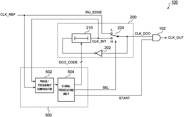
1. A PLL circuit structured as a Phase Locked Loop (PLL) circuit, comprising:
a digitally controlled oscillator structured such that, during a period in which a selection signal is asserted, a ring oscillator is formed so as to oscillate at a frequency that is changed based on a control code, and such that, during a period in which the selection signal is negated, an injection edge based on a reference clock can be injected; and
a controller structured to control the digitally controlled oscillator,
wherein (A) in a startup period of the PLL circuit, the controller is set to a first mode, and repeats a cycle comprising (i) a process in which the selection signal is asserted so as to oscillate the digitally controlled oscillator, and phase comparison is made between an oscillator clock generated by the digitally controlled oscillator and the reference clock, and (ii) a process in which the selection signal is negated so as to stop the digitally controlled oscillator, and the control code is updated by a binary search based on a result of the phase comparison.
|