| CPC H03F 3/45475 (2013.01) [H01Q 1/248 (2013.01); H03F 1/26 (2013.01); H03F 3/195 (2013.01); H03F 2200/451 (2013.01); H03F 2203/45568 (2013.01); H03F 2203/45594 (2013.01)] | 16 Claims |

|
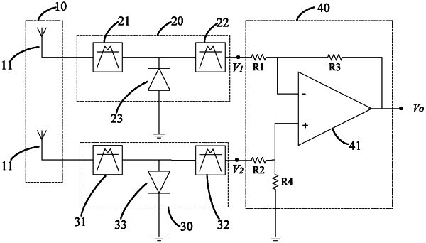
1. An amplifying circuit, comprising:
a first rectifying circuit, configured to output a first direct current signal according to a first alternating current signal;
a second rectifying circuit, configured to output a second direct current signal according to a second alternating current signal;
a differential amplifying circuit, configured to receive the first direct current signal and the second direct current signal, amplify a difference between the first direct current signal and the second direct current signal, and output an amplified difference between the first direction current signal and the second direct current signal,
wherein the first direct current signal and the second direct current signal have directions opposite to each other, the first rectifying circuit comprises at least one of a first band-pass filter and a first low-pass filter,
the first rectifying circuit comprises a first input terminal configured to receive the first alternating current signal, and a first output terminal configured to output the first direct current signal; and the second rectifying circuit comprises a second input terminal configured to receive the second alternating current signal, and a second output terminal configured to output the second direct current signal,
the first rectifying circuit further comprises a first rectifier connected between the first input terminal and the first output terminal, and the first rectifier is configured to perform a half-wave rectification on the first alternating current signal as received, to output a first pulsating direct current signal; the second rectifying circuit further comprises a second rectifier connected between the second input terminal and the second output terminal, and the second rectifier is configured to perform a half-wave rectification on the second alternating current signal as received, to output a second pulsating direct current signal;
wherein the first pulsating direct current signal and the second pulsating direct current signal have directions opposite to each other,
the first rectifying circuit further comprises the first band-pass filter and the first low-pass filter;
the first band-pass filter is connected between the first input terminal and the first rectifier, and is configured to perform a band-pass filtering on the first alternating current signal input from the first input terminal, and output a band-pass filtered signal to the first rectifier; and
the first low-pass filter is connected between the first rectifier and the differential amplifying circuit, and is configured to perform a low-pass filtering on the first pulsating direct current signal output by the first rectifier to output the first direct current signal.
|