| CPC H02M 7/5387 (2013.01) [H02M 1/38 (2013.01); H02M 5/4585 (2013.01); H02M 7/48 (2013.01); H02M 7/5395 (2013.01); H02M 1/0038 (2021.05); H02M 1/0067 (2021.05); H02M 1/008 (2021.05); H02M 1/385 (2021.05); H02P 9/305 (2013.01); H02P 27/06 (2013.01)] | 14 Claims |

|
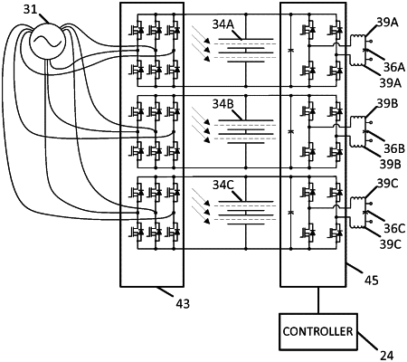
1. An isolated bus inverter system comprising:
a plurality of inverter circuits including a switching array, each inverter circuit of the plurality of inverter circuits configured to provide a respective alternating current (AC) signal to an output, wherein each of the plurality of inverter circuits is connected to a respective energy source isolated on respective input sides of the plurality of inverter circuits from the respective energy sources of the other inverter circuits of the plurality of inverter circuits;
a plurality of rectifier circuits configured to each supply respective direct current (DC) signals to the respective ones of the plurality of inverter circuits, wherein at least one of the plurality of rectifier circuits is connected to one of the plurality of inverter circuits;
a controller configured to generate timing signals for the plurality of inverter circuits to generate the respective AC signals for the output based on the DC signals received from the plurality of rectifier circuits; and
an alternator comprising inductively-coupled windings and configured to provide respective AC power to the plurality of rectifier circuits;
wherein the plurality of rectifier circuits are synchronous rectifier circuits configured to drive the alternator in reverse to transfer power to another one of the plurality of rectifier circuits via the respective windings.
|