| CPC H02K 7/145 (2013.01) [B25B 21/02 (2013.01); B25F 5/00 (2013.01); B25F 5/008 (2013.01); H02K 5/04 (2013.01); H02K 9/06 (2013.01); H02K 11/215 (2016.01); H02K 11/33 (2016.01); H02K 11/38 (2016.01); H02K 21/046 (2013.01); H02K 29/08 (2013.01); H05K 1/0203 (2013.01); H05K 1/113 (2013.01); H05K 1/18 (2013.01); H05K 7/20136 (2013.01); H05K 7/20436 (2013.01); H02K 2211/03 (2013.01); H05K 2201/10053 (2013.01); H05K 2201/10151 (2013.01)] | 20 Claims |

|
1. A power tool comprising:
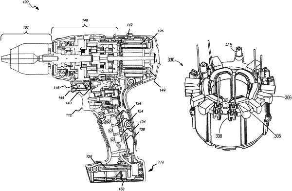
a housing having a motor housing portion, a handle portion, and a battery pack interface,
wherein the handle portion spatially connects the motor housing portion and the battery interface, and
wherein the battery interface is configured to removably receive and support a battery pack;
a brushless direct current (DC) motor within the motor housing portion and having a rotor and a stator, wherein the rotor is coupled to a motor shaft to produce an output outside of the housing, wherein the motor shaft is configured to rotate about a longitudinal axis, which extends through the motor shaft;
a combined printed circuit board (PCB) having a Hall sensor and power switching elements configured to drive the brushless DC motor,
wherein the power switching elements are mounted on the combined PCB in a flat orientation,
wherein the longitudinal axis extends through the combined PCB, and
wherein the combined PCB includes a plurality of motor lead pads that each include an opening cut out from an outer peripheral edge of the combined PCB, each motor lead pad configured to receive a motor lead wire of the stator;
a heat sink attached to an end of the brushless DC motor, wherein the heat sink includes a through-hole,
wherein the Hall sensor is located radially inward of the through-hole,
wherein the heat sink is located between the brushless DC motor and the combined PCB, and
wherein at least one of the motor lead wires passes through the heat sink such that a portion of the at least one motor lead wire that is located in a plane defined by the heat sink and perpendicular to the longitudinal axis is fully enclosed by the heat sink; and
a processor and a memory, the processor configured to receive motor positional information from the Hall sensor and control the power switching elements to drive the brushless DC motor.
|